
Arrangement structure of evacuation passages for a highway-rail joint construction shield tunnel

An evacuation channel and shield tunnel technology, applied in the field of tunnels, can solve the problems of inability to arrange stairwells, affecting the safety of evacuees, and unfavorable evacuation, and achieve the effects of improving evacuation safety, shortening evacuation time, and improving evacuation efficiency.

Active Publication Date: 2016-04-13
CHINA RAILWAY SIYUAN SURVEY & DESIGN GRP
View PDF6 Cites 0 Cited by
  • Summary
  • Abstract
  • Description
  • Claims
  • Application Information

AI Technical Summary

Problems solved by technology

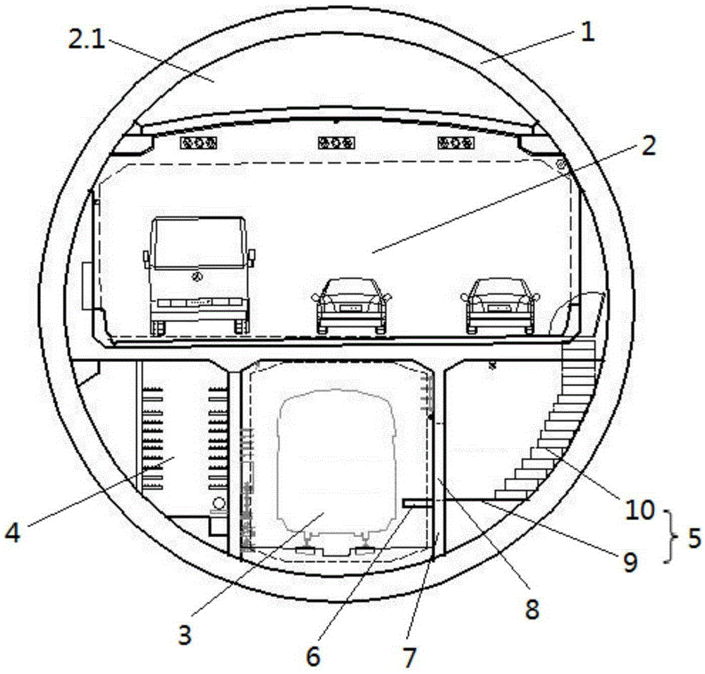
[0003] The existing highway-rail joint construction shield tunnel arranges the running surface of the evacuation passage and the evacuation platform surface of the rail transit hole at the same elevation. This arrangement has the following disadvantages: 1. The position of the evacuation passage in the structural section is too low. The circular section of the tunnel makes the width of the evacuation channel too narrow, which is not conducive to evacuation, especially at the connection between the evacuation channel and the road layer, the width is even smaller; while ensuring the connection between the evacuation channel and the subway evacuation platform at the same elevation, how to increase the The width of the large evacuation channel; 2. The evacuation channel and the road layer are connected by stairs (or slides). Due to the small width of the evacuation channel, stairwells cannot be arranged. Road) into the evacuation channel, affecting the safety of evacuated personnel

Method used


Image

  • Arrangement structure of evacuation passages for a highway-rail joint construction shield tunnel
  • Arrangement structure of evacuation passages for a highway-rail joint construction shield tunnel
  • Arrangement structure of evacuation passages for a highway-rail joint construction shield tunnel

Examples


Embodiment Construction

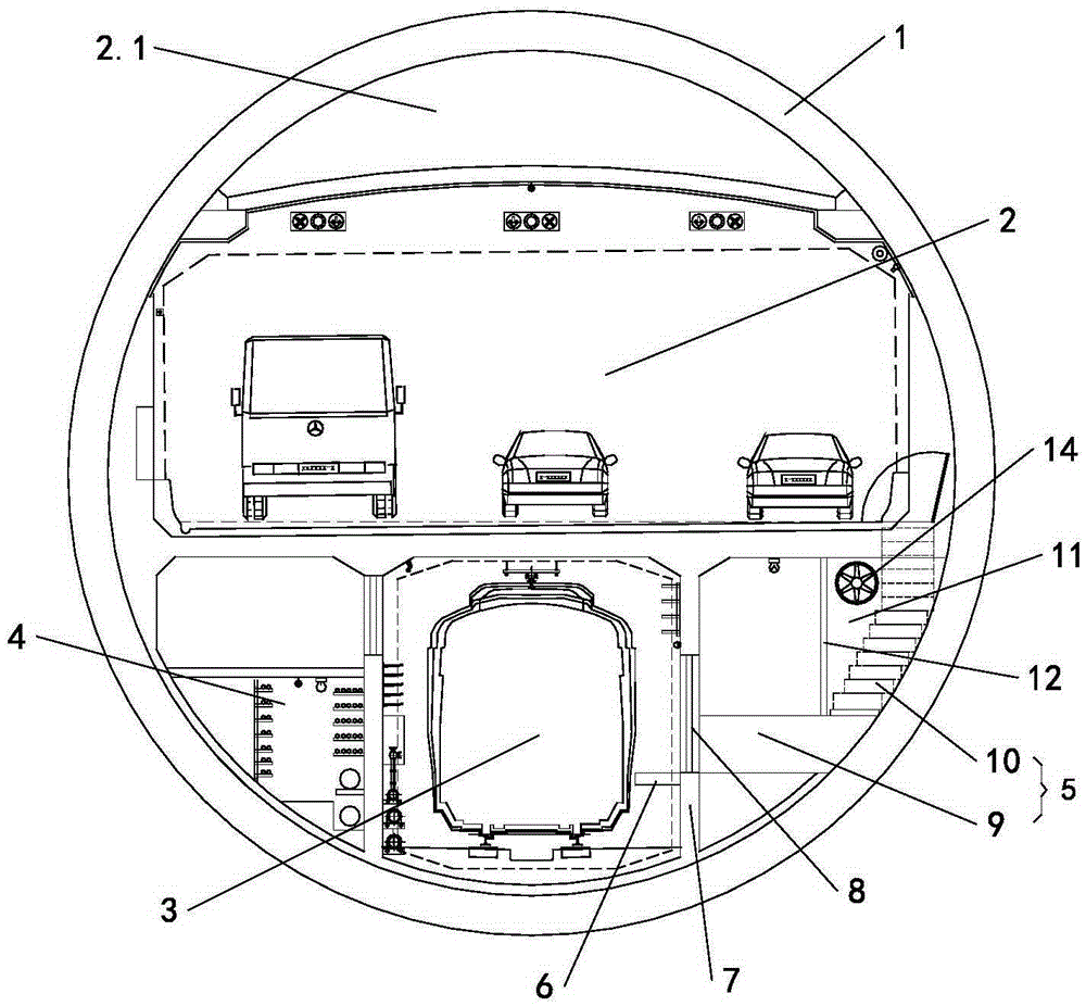
[0018] Such as figure 1 As shown, the highway-rail joint construction shield tunnel includes a shield tunnel segment 1, a road lane 2 is provided in the shield tunnel segment 1, and a special road smoke exhaust duct 2.1 is provided in the road lane 2 and at the top, A rail transit passage area 3 is set in the middle part below the highway lane 2; a pipeline corridor 4 is arranged on one side of the rail transit passage area 3, and a personnel evacuation channel 5 is arranged on the other side; a lateral evacuation platform is arranged in the rail transit passage area 3 6. A partition wall 7 is provided between the rail transit area 3 and the evacuation passage 5. One side of the partition wall 7 is the evacuation passage 5, and the other side is the lateral evacuation platform 6. On the partition wall 7, there is The first fire door 8 ; the evacuation passage 5 includes a running surface 9 and a staircase 10 , and the staircase 10 communicates the evacuation passage 5 and the ...


PUM


Abstract

The invention discloses an evacuation route arrangement structure for a combined highway and metro shield tunnel. The structure comprises a lateral evacuation platform and an evacuation route, wherein a first fireproof door is arranged between the lateral evacuation platform and the evacuation route; the evacuation route comprises a walking plane and stairs; the walking plane comprises a low walking plane on the same elevation with the lateral evacuation platform, a high walking plane at the same elevation of an entrance of the stairs and a gentle slope for connecting the low and high walking planes; the stairs are positioned in a stair well, and the stair well consists of a stair well partition wall and a shield tunnel pipe piece; a second fireproof door is arranged on the stair well partition wall between the high walking plane and the stairs; a pressurization fan is arranged another stair well partition wall opposite to the second fireproof door. According to the structure, the width of the evacuation route is greatly increased, the evacuation time is shortened, and the evacuation efficiency is improved; in addition, the evacuation route is prevented from being invaded by fire smoke on a highway layer, so that the evacuation safety is improved.

Description

technical field [0001] The invention relates to tunnels, in particular to an arrangement structure of tunnel evacuation passages, in particular to an arrangement structure of evacuation passages of tunnels with a shield structure built together with highways and railways. Background technique [0002] With the vigorous development of urban construction, the continuous expansion of population size and the sharp increase of traffic flow, the pressure on urban traffic is increasing. In order to save land resources, the construction of underground projects such as large-scale underground urban road tunnels and rail transit has entered a stage of rapid development. The more the shield method is used to build. [0003] The existing highway-rail joint construction shield tunnel arranges the running surface of the evacuation passage and the evacuation platform surface of the rail transit hole at the same elevation. This arrangement has the following disadvantages: 1. The position o...

Claims


Application Information

Patent Timeline
Patent Type & Authority Patents(China)
IPC IPC(8): E21D9/14E21F11/00
Inventor 肖明清孙文昊彭长胜焦齐柱何应道魏重丽
Owner CHINA RAILWAY SIYUAN SURVEY & DESIGN GRP
Learn More