
Die-assembling mechanism in hollow plastic molding machine

A mold clamping mechanism and molding machine technology, which is applied in the field of blow molding machines, can solve the problems of increasing the workload of technical staff and different stroke positions of multiple piston rods, and achieve the effects of simple structure, long service life and convenient operation

Inactive Publication Date: 2014-03-26
SUZHOU HUAWANG MACHINERY
View PDF0 Cites 2 Cited by
  • Summary
  • Abstract
  • Description
  • Claims
  • Application Information

AI Technical Summary

Problems solved by technology

[0002] In the opening and closing mechanism of the two templates, the traditional clamping cylinder is a single-head piston rod mechanism. When the size of the template in the opening and closing mechanism of the two templates increases, the number of corresponding clamping cylinders will increase. It has become a difficult problem to control the stroke position of the piston rod of the clamping cylinder. The traditional method is: install a pipe-type one-way throttle valve on the cylinder to adjust the stroke position of the piston rod of the clamping cylinder; When the temperature of the hydraulic oil changes and the flow and pressure of the hydraulic oil change, the stroke position of the piston rod of the cylinder will change again, and the stroke positions of multiple piston rods will be different, so frequent adjustments must be made, and the piston rods should be adjusted at the same time. The stroke position of the rod requires the technical staff to have high technical requirements, and at the same time have several years of operating experience, which increases the workload of the technical staff

Method used


Image

  • Die-assembling mechanism in hollow plastic molding machine
  • Die-assembling mechanism in hollow plastic molding machine
  • Die-assembling mechanism in hollow plastic molding machine

Examples


Embodiment Construction

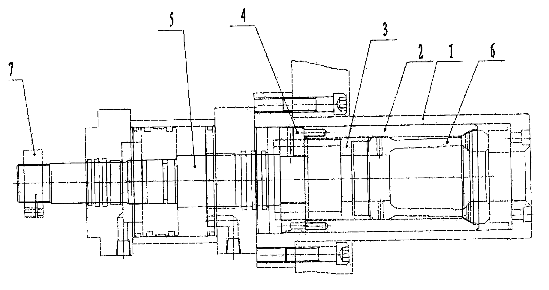
[0012] As shown in the accompanying drawings, the piston rod in the clamping cylinder is made into a double-headed piston rod 10, one end is connected with the lock buckle 11, and the other end is equipped with an adjusting nut 12 and a lock nut 13 that can adjust the stroke position of the piston rod, and at the same time Add locking screws; according to the thickness of the mold 21 and mold 22 in the mold opening and closing mechanism diagram, the position of the adjusting nut 12 can be adjusted arbitrarily to ensure the correct position of the lock. At the same time, the stroke of the piston rod of the mold locking cylinder can be added or subtracted arbitrarily. , and install a detection device to shorten the travel time of the clamping cylinder; this design can reduce the workload and operating experience of technical staff, the pressure and flow of hydraulic oil entering the clamping cylinder can be adjusted arbitrarily, and the temperature of the hydraulic oil will Chang...


PUM


Abstract

The invention relates to a blowing machine and in particular relates to a die-assembling mechanism in a hollow plastic molding machine. The die-assembling mechanism comprises templates, a die, die locking oil cylinders and die locking mechanisms, wherein the die locking oil cylinders are arranged on the antiplane of the templates; the multiple die locking oil cylinders can be randomly arranged on the two templates; the corresponding die locking mechanisms are arranged on the templates opposite to the die locking oil cylinders; lock catches of the die locking oil cylinders can enter the inner cavities of clamping sleeves in the die locking mechanisms; piston rods in the oil cylinders of the die locking mechanisms drive shaping sleeves to move forwards; one end of each clamping sleeve is conveyed into the inner cavity of the corresponding shaping sleeve; tightening slots in the clamping sleeves are narrowed, so that cylinders which are the same as the alcove cavities on the lock catches are formed at the front ends of the clamping sleeves, and the lock catches can be locked. The die-assembling mechanism disclosed by the invention is simple in structure, convenient to operate and long in service life.

Description

technical field [0001] The invention relates to a blow molding machine, in particular to a mold clamping mechanism in a hollow plastic molding machine. Background technique [0002] In the opening and closing mechanism of the two templates, the traditional clamping cylinder is a single-head piston rod mechanism. When the size of the template in the opening and closing mechanism of the two templates increases, the number of corresponding clamping cylinders will increase. It has become a difficult problem to control the stroke position of the piston rod of the clamping cylinder. The traditional method is: install a pipe-type one-way throttle valve on the cylinder to adjust the stroke position of the piston rod of the clamping cylinder; When the temperature of the hydraulic oil changes and the flow and pressure of the hydraulic oil change, the stroke position of the piston rod of the cylinder will change again, and the stroke positions of multiple piston rods will be different,...

Claims


Application Information

Patent Timeline
Patent Type & Authority Applications(China)
IPC IPC(8): B29C49/56
Inventor 周振忠
Owner SUZHOU HUAWANG MACHINERY
Learn More