
Clamping mechanism of rebar straightening device

A clamping mechanism and a technology for steel bars, which are applied in the field of clamping mechanisms of steel bar straightening devices, can solve the problem of no steel bar straightening device, etc., and achieve the effects of convenient straightening operation, large contact area, and enhanced clamping force

Active Publication Date: 2015-05-06
青岛昊河水泥制品有限责任公司
View PDF5 Cites 0 Cited by
  • Summary
  • Abstract
  • Description
  • Claims
  • Application Information

AI Technical Summary

Problems solved by technology

Before carrying out the seam welding forming process, the steel bar needs to be straightened first to ensure that the steel bar can pass through the steel bar piercing of the seam welder smoothly. However, there is no special steel bar straightening device in the prior art. Based on this, the prior art needs further Improve

Method used


Image

  • Clamping mechanism of rebar straightening device
  • Clamping mechanism of rebar straightening device

Examples


Embodiment Construction

[0018] Below in conjunction with accompanying drawing and specific embodiment the present invention is described in further detail:

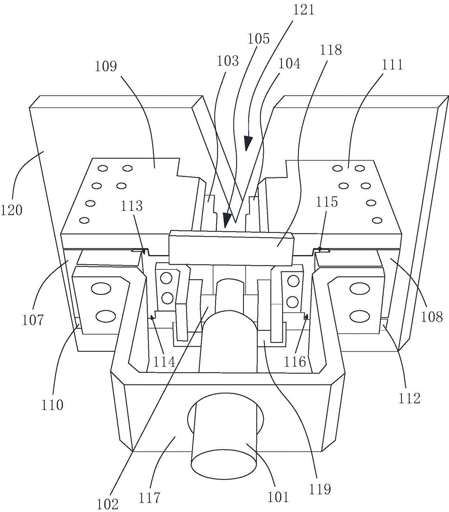
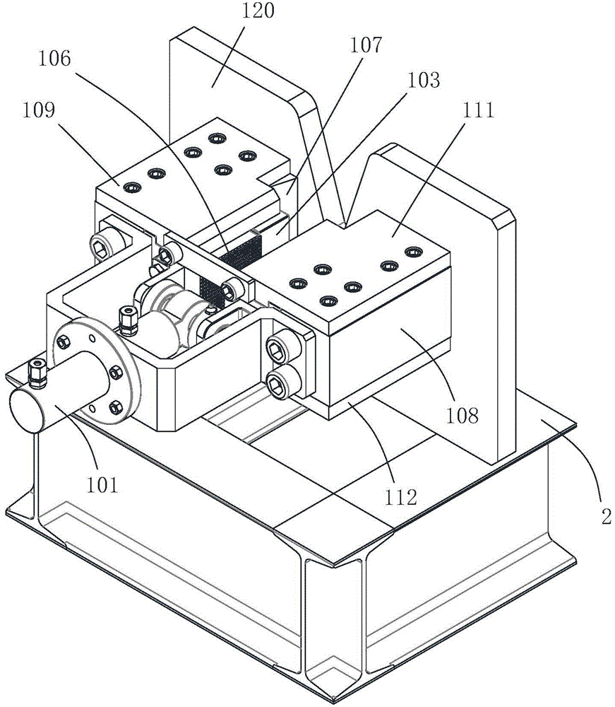
[0019] combine figure 1 , figure 2 As shown, the clamping mechanism of the steel bar straightening device is arranged at one end of the steel bar straightening device for clamping and fixing the steel bar. The clamping mechanism of the steel bar straightening device includes a power cylinder 101 , a transmission rod 102 , a left clamping block 103 and a right clamping block 104 . With one end where the power cylinder is set as the front end, the power cylinder, the transmission rod, and the whole composed of the left clamping block and the right clamping block are sequentially arranged from the front to the rear. The transmission rod is arranged along the length direction perpendicular to the steel bars, the piston rod of the power cylinder is connected to the middle part of the transmission rod, and the left clamping block and the right clam...


PUM


Abstract

The invention discloses a clamping mechanism of a rebar straightening device. The clamping mechanism comprises a power cylinder, a drive rod, a left clamping block and a right clamping block. The drive rod is arranged in the direction perpendicular to the length direction of rebars, and a piston rod of the power cylinder is connected to the middle of the drive rod. The left clamping block and the right clamping block are connected to the left end and the right end of the drive rod respectively, the right side face of the left clamping block and the left side face of the right clamping block are opposite and both parallel to the length direction of the rebars, and a rebar clamping region is formed between the right side face of the left clamping block and the left side face of the right clamping block. A left side inclined guide block is arranged in the left side direction of the left clamping block, a right side inclined guide block is arranged in the right side direction of the right clamping block, the interval between the left side inclined guide block and the right side inclined guide block linearly increases or decreases in the length direction of the rebars, and the left clamping block and the right clamping block synchronously move along the left side inclined guide block and the right side inclined guide block respectively. The clamping mechanism can effectively clamp the rebars.

Description

technical field [0001] The invention relates to a clamping mechanism of a steel bar straightening device. Background technique [0002] The main reinforcement of the prefabricated high-strength concrete square pile reinforcement cage is made of HRB400 rebar, which is formed by automatic seam welding, saving time and effort, and the quality is easily guaranteed. In the seam welding production line of the steel cage, it generally needs to go through the process of butt welding-grinding-cutting-roll welding forming. Before carrying out the seam welding forming process, the steel bar needs to be straightened first to ensure that the steel bar can pass through the steel bar piercing of the seam welder smoothly. However, there is no special steel bar straightening device in the prior art. Based on this, the prior art needs further Improve. Contents of the invention [0003] The purpose of the present invention is to provide a clamping mechanism of a steel bar straightening dev...

Claims


Application Information

Patent Timeline
Patent Type & Authority Patents(China)
IPC IPC(8): B21F1/02
Inventor 王传波隋耀文田斌王风民邓国威
Owner 青岛昊河水泥制品有限责任公司
Learn More