
Upper die clamp-type hydraulic clamping device of bending machine

A hydraulic clamping and die clamping technology, which is applied in metal processing equipment, forming tools, manufacturing tools, etc., can solve the problems of short service life of hydraulic cylinders, high labor intensity of operators, and poor positioning accuracy of upper dies, etc. High mold positioning accuracy, compact structure, and high mold clamping positioning accuracy

Inactive Publication Date: 2014-03-26
HUANGSHI HUAXIN MACHINERY EQUIP
View PDF0 Cites 11 Cited by
  • Summary
  • Abstract
  • Description
  • Claims
  • Application Information

AI Technical Summary

Problems solved by technology

[0003] The purpose of the present invention is to solve the problems of low efficiency of mold changing operation, high labor intensity of operators, poor positioning accuracy of the upper mold and short service life of the hydraulic cylinder existing in the existing clamping device of the upper mold of the hydraulic bending machine, and provide a Upper Die Clamp Type Hydraulic Clamping Device of a Bending Machine

Method used


Image

  • Upper die clamp-type hydraulic clamping device of bending machine
  • Upper die clamp-type hydraulic clamping device of bending machine
  • Upper die clamp-type hydraulic clamping device of bending machine

Examples


Embodiment

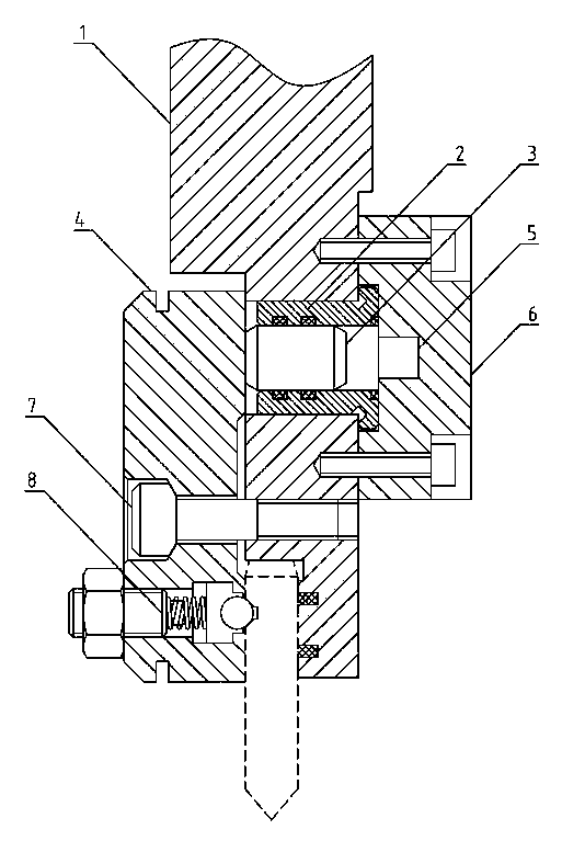
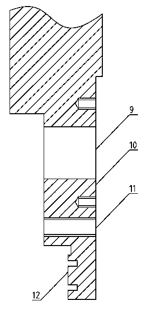
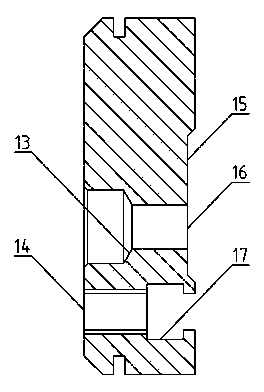
[0016] Embodiment: (see for details figure 1 ) A clamp-type hydraulic clamping device for a bending machine, which is provided with a driving slider 1 and a plunger hydraulic cylinder 2, and the lower end of the driving slider 1 is provided with a mounting plate 10 (see figure 2 ), the mounting plate 10 is respectively provided with mounting holes 9, connecting screw holes 11 and clamping positions 12; especially: the plunger hydraulic cylinder 2 is installed in the mounting holes 9 on the mounting plate 10 of the drive slider 1, and the mounting plate 10 is located on one side of the cylinder body of the plunger hydraulic cylinder 2, and a pressure plate 6 is installed, and the mounting plate 10 is located on the other side of the piston rod 3 of the plunger hydraulic cylinder 2, and a clamping plate 4 is installed with a ball screw 7, and the clamping plate 4 There is a card slot 17 below (see image 3 ), a tensioning mechanism 8 is installed in the card slot 17 of the cl...


PUM


Abstract

The invention relates to improvement for upper die clamping devices of bending machines, in particular to an upper die clamp-type hydraulic clamping device of a bending machine. The upper die clamp-type hydraulic clamping device of the bending machine comprises a driving sliding block and a plunger hydraulic oil cylinder. The upper die clamp-type hydraulic clamping device of the bending machine is characterized in that the plunger hydraulic oil cylinder is arranged in a mounting hole in a mounting plate of the driving sliding block, a press plate is arranged on one side, located on a cylinder body of the plunger hydraulic oil cylinder, of the mounting plate, a clamping plate is arranged on the other side, located on a piston rod of the plunger hydraulic oil cylinder, of the mounting plate through ball screws, a clamping groove is formed in the lower portion of the clamping plate, and a tensioning mechanism is arranged in the clamping groove of the clamping plate. The upper die clamp-type hydraulic clamping device of the bending machine solves the problems that the upper die clamping device of the existing bending machine is low in die change operation efficiency, the labor intensity of operation personnel is large, upper die locating accuracy is poor, and the service life of a hydraulic oil cylinder is short. The upper die clamp-type hydraulic clamping device of the bending machine is mainly used for the improvement of the upper die clamping devices of the existing bending machines.

Description

technical field [0001] The invention relates to an improvement of an upper die clamping device of a hydraulic bending machine, which is a clamp-type hydraulic clamping device for an upper die of a bending machine. Background technique [0002] The hydraulic bending machine driving slider is equipped with an upper mold clamping device, which is used to clamp the bending upper mold; the prior art hydraulic bending machine upper mold clamping device mainly includes a pressure plate clamping structure and a hydraulic clamping clamp. Clamping structure, the clamping structure of the clamping plate is to use the clamping force between the fastening screw on the splint and the driving slider to realize the clamping of the upper die, and the clamping structure of the hydraulic clamping is to use the head of the piston rod of the hydraulic cylinder and the The clamping force between the driving sliders realizes the clamping of the upper die; the problems existing in the clamping devi...

Claims


Application Information

Patent Timeline
IPC IPC(8): B21D37/04
Inventor 黄俊石欢
Owner HUANGSHI HUAXIN MACHINERY EQUIP
Learn More