Turboshaft Engine Compressor Case Spraying Method and Its Protective Fixture

A technology for turboshaft engines and compressors, which can be used in coatings, devices for coating liquids on surfaces, and pre-treated surfaces, etc., and can solve problems such as easy deformation of casings

Active Publication Date: 2016-01-06
CHINA HANGFA SOUTH IND CO LTD
View PDF3 Cites 0 Cited by
  • Summary
  • Abstract
  • Description
  • Claims
  • Application Information

AI Technical Summary

Problems solved by technology

[0003] The purpose of the present invention is to provide a turboshaft engine compressor casing spraying method and its protective fixture to solve the technical problem that the casing of the turboshaft engine in the prior art is easily deformed when the casing is sprayed and sealed with a coating thickness ≥ 1 mm.

Method used


Image

  • Turboshaft Engine Compressor Case Spraying Method and Its Protective Fixture
  • Turboshaft Engine Compressor Case Spraying Method and Its Protective Fixture
  • Turboshaft Engine Compressor Case Spraying Method and Its Protective Fixture

Examples


Embodiment Construction

[0030] The embodiments of the present invention will be described in detail below with reference to the accompanying drawings, but the present invention can be implemented in many different ways defined and covered by the claims.

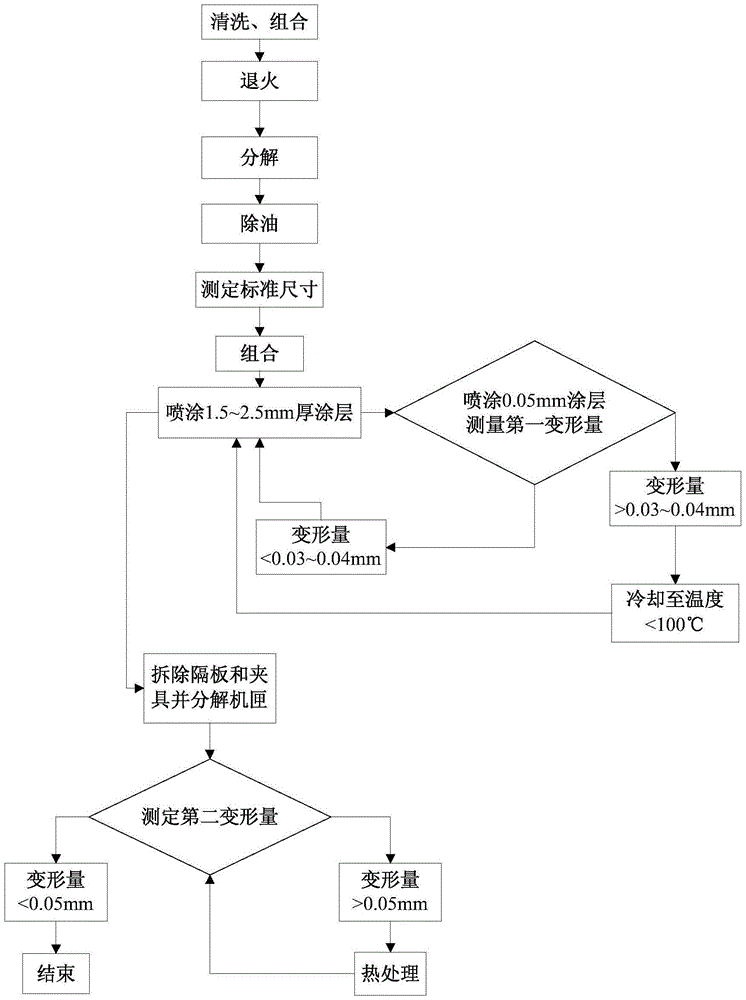
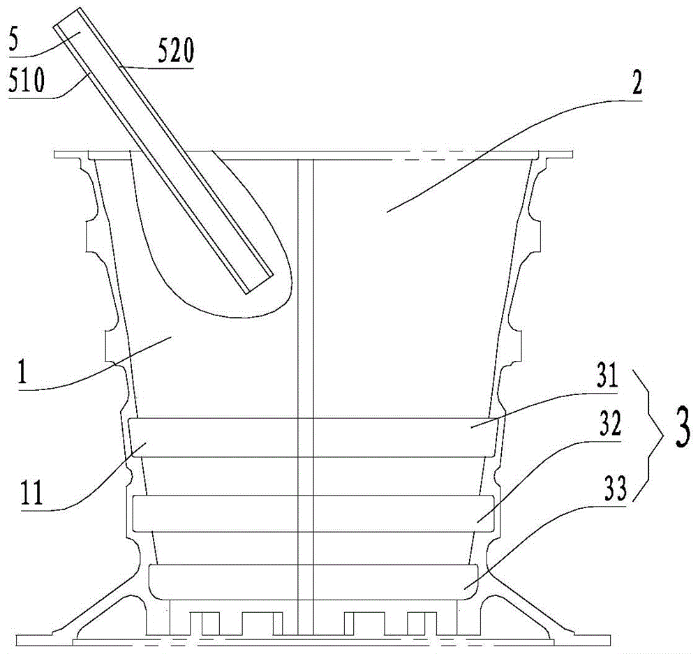
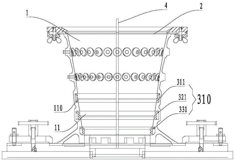
[0031] In the turboshaft engine compressor casing spraying method provided by the present invention, the first casing 1 and the second casing 2 are combined for spraying. The deformation caused by spraying after the combination of the first casing 1 and the second casing 2 will be digested inside the casing, and combined with heat treatment, shot blasting and other processes to control the deformation of the casing after spraying coating within 0.05mm.

[0032] see figure 1 , the method includes the following steps:

[0033] 1) Measuring the standard size: measure the size of the first casing 1 and the second casing 2 to obtain the standard size. The first casing 1 and the second casing 2 are combined according to a conventional method. Obviously...


PUM


Abstract

The invention provides a method for spraying a gas compressor case of a turbo-shaft engine and a protective clamp used in the method. The method comprises the steps of case assembly, standard size determination, coating spraying and disassembly. The total deformation of the case which is sprayed by using the method is smaller than 0.05mm.

Description

technical field [0001] The present invention relates to the field of aero-engine compressor casings, in particular, to a spraying method for turboshaft engine compressor casings, and another aspect of the present invention provides a protective fixture used in the spraying method. Background technique [0002] Turboshaft engines are commonly used in aeroengines, and the compressor casing of the turboshaft engine consists of two semicircular casings. The casing is small in size, poor in rigidity, and long in depth and diameter. In order to control the gap between the rotor and the stator and improve the airtightness of the engine, it is often necessary to seal the coating with a thickness greater than or equal to 1mm in the casing. The existing spraying method is to divide the casing into two and spray separately and then assemble and process. However, the casing is small in size and poor in rigidity, and it is difficult to control deformation when spraying with this method...

Claims


Application Information

Patent Timeline
Patent Type & Authority Patents(China)
IPC IPC(8): B05C11/02B05C13/02B05D1/02B05D3/00
Inventor 郭志宏胡祥松周伟祥许辉汪云程马永清
Owner CHINA HANGFA SOUTH IND CO LTD
Why Eureka
Try Eureka