Intelligent flexion fitness equipment system
A technology of fitness equipment and knuckle body, which is applied in the field of fitness equipment system, can solve the problems of single working mode, incapable of intelligent display, and non-adjustable fitness intensity of knuckle fitness equipment, so as to maintain the health of the body and facilitate daily fitness and physical examination , a wide range of effects
- Summary
- Abstract
- Description
- Claims
- Application Information
AI Technical Summary
Problems solved by technology
Method used
Image
Examples
Embodiment 1
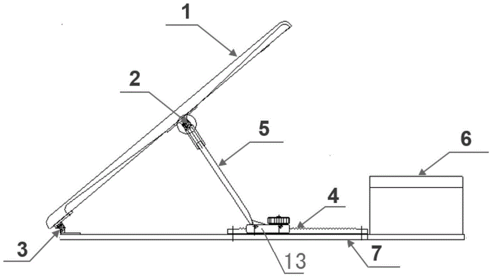
[0031] The fitness module is structured like figure 1 As shown, it includes a base 7 , a support panel 1 , a hinge 3 , a panel support 5 and a sliding mechanism formed by a tooth groove 4 and a slider 13 . The base 7 is the support plane of the intelligent body-building exercise system, and is used to support the whole exercise system. The ends of the support panel 1 and the base 7 are connected by a hinge 3 , and the support panel 1 can rotate around the hinge point to change the angle between the support panel 1 and the base 7 . Anti-slip design is carried out on the upper surface of the support panel 1, that is, a rubber material with a large friction coefficient and a pattern is laid. When the user uses the fitness system, he stands on the support panel 1 to perform flexion exercises. The base 7 is provided with two parallel tooth grooves with the same tooth structure, and a slider is placed in each tooth groove, and the slider can slide in the corresponding tooth groove....
Embodiment 2
[0037] In order to facilitate the adjustment of the angle between the support panel 1 and the base 7, this embodiment provides another structural form of the sliding mechanism in the fitness module. The sliding mechanism in this embodiment includes a slider, a chute, a motor and a worm gear. Wherein the chute is located on the upper surface of the base 7, a slide block is placed in the chute, and the slide block can slide in the chute. One end of the panel support 5 is hinged to the lower surface of the support panel 1 , and the other end is fixedly connected to the slider in the chute for supporting the support panel 1 . The output shaft of the motor is connected to the worm gear, the worm gear is engaged with the worm, the worm is placed parallel to the chute, and the worm is fixedly connected to the slider; when the angle between the support panel 1 and the base 7 needs to be adjusted, the motor is started, and the motor passes through a The worm gear with locking performa...
PUM
 Abstract
Description
Claims
Application Information
 - R&D
- Intellectual Property
- Life Sciences
- Materials
- Tech Scout
- Unparalleled Data Quality
- Higher Quality Content
- 60% Fewer Hallucinations
Browse by: Latest US Patents, China's latest patents, Technical Efficacy Thesaurus, Application Domain, Technology Topic, Popular Technical Reports.
© 2025 PatSnap. All rights reserved.Legal|Privacy policy|Modern Slavery Act Transparency Statement|Sitemap|About US| Contact US: help@patsnap.com


