2-12GHz broadband microwave front-end circuit and 2-12GHz microwave signal receiving method

A front-end circuit and microwave technology, applied in electrical components, transmission systems, etc., can solve the problems of equipment weight and large microwave front-end volume, and achieve the effect of higher weight, improved noise coefficient and intermediate frequency output flatness index, and small size.

Active Publication Date: 2014-03-19
NO 8511 RES INST OF CASIC
View PDF4 Cites 19 Cited by
  • Summary
  • Abstract
  • Description
  • Claims
  • Application Information

AI Technical Summary

Problems solved by technology

This implementation method has the advantages of good performance indicators, convenient installation and debugging, etc., but the entire microwave front-end is large in size and heavy in equipment, and it is only suitable for some platforms such as vehicles and laboratories that do not require high volume and weight, and has certain limitations.

Method used


Image

  • 2-12GHz broadband microwave front-end circuit and 2-12GHz microwave signal receiving method
  • 2-12GHz broadband microwave front-end circuit and 2-12GHz microwave signal receiving method
  • 2-12GHz broadband microwave front-end circuit and 2-12GHz microwave signal receiving method

Examples


Embodiment Construction

[0030] In order to better understand the technical content of the present invention, specific embodiments are given together with the attached drawings for description as follows.

[0031] The implementation of the present invention will be described in detail below in conjunction with the accompanying drawings and embodiments.

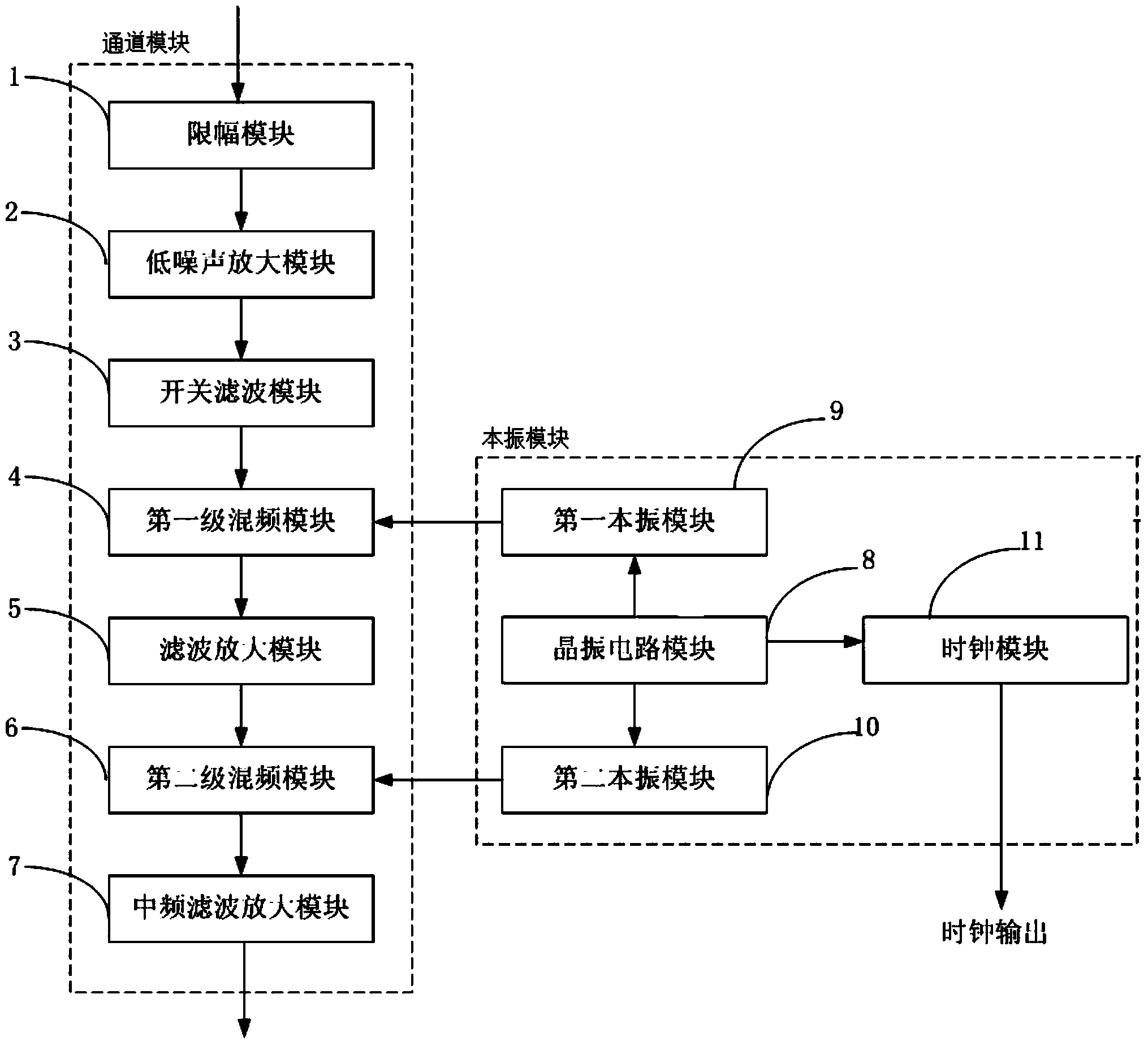
[0032] figure 1 It is a circuit structure of a 2-12GHz broadband microwave front-end circuit in an embodiment of the present invention, wherein a 2-12GHz broadband microwave front-end circuit includes a channel module and a local oscillator module, and the local oscillator module is connected to the channel module to provide local vibration signal.

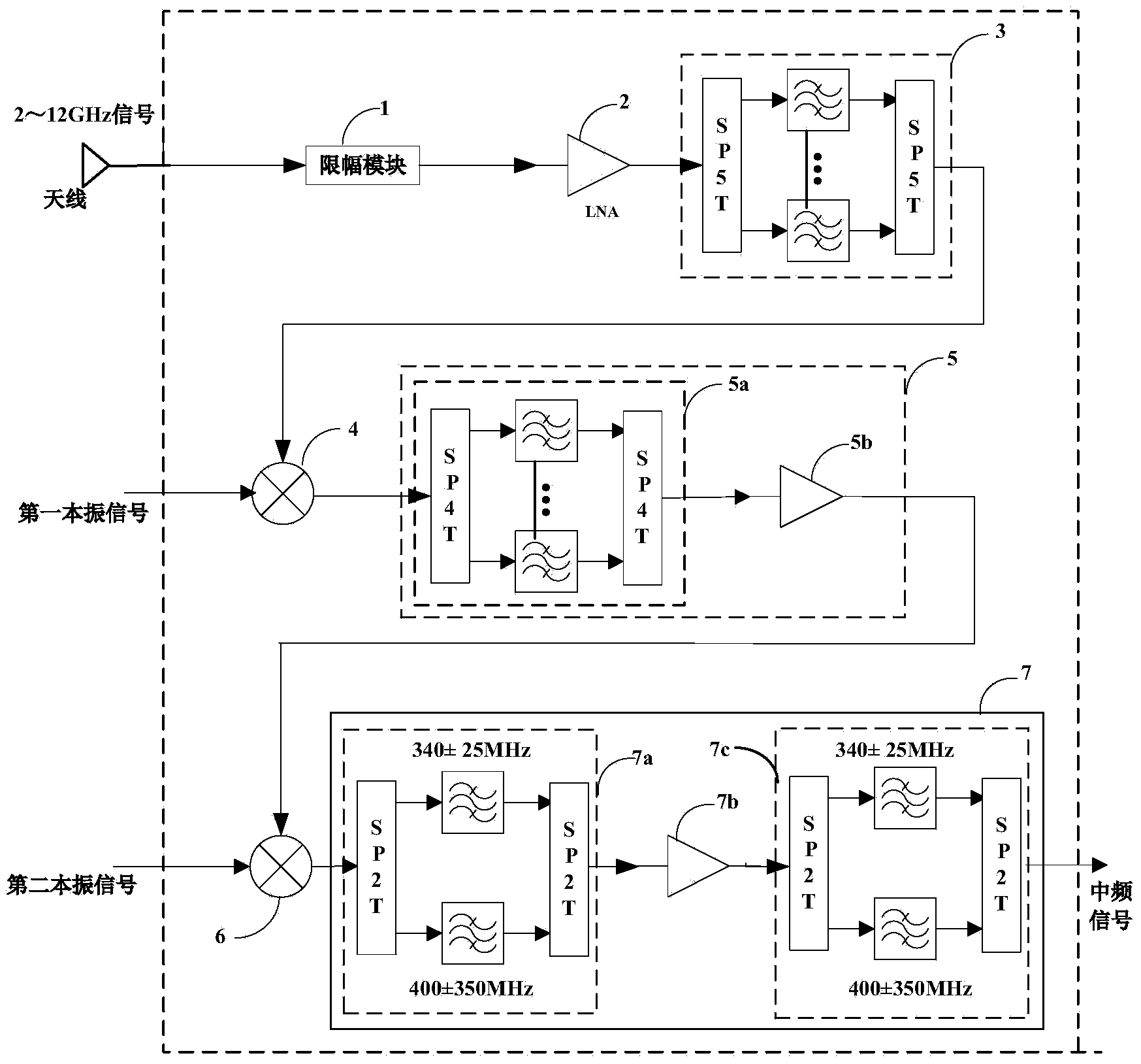
[0033] to combine figure 2 As shown, the channel module includes a limiter module 1 , a low noise amplifier module 2 , a switch filter module 3 , a first-stage frequency mixing module 4 , a filter amplifier module 5 , a second-stage frequency mixer module 6 and an intermediate frequency filter amplifie...


PUM


Abstract

The invention provides a 2-12GHz broadband microwave front-end circuit and a 2-12GHz microwave signal receiving method. The front-end circuit comprises a channel module and a local oscillator module. The local oscillator module is connected with the channel module and provides local oscillator signals for the channel module. The channel module comprises an amplitude limiting module, a low-noise amplification module, a switch filtering module, a primary frequency mixing module, a filtering amplification module, a secondary frequency mixing module and a medium frequency filtering amplification module. The local oscillator module comprises a crystal oscillator circuit module, a first local oscillator module, a second local oscillator module and a clock module. The first local oscillator module, the second local oscillator module and the clock module are respectively connected with the crystal oscillator circuit module, the crystal oscillator circuit module amplifies crystal oscillator signals output by a crystal oscillator and divides the crystal oscillator signals into three ways, and the crystal oscillator signals are respectively output to the first local oscillator module, the second local oscillator module and the clock module to serve as reference signals. The first local oscillator module is connected with the primary frequency mixing module and provides local oscillator signals for the primary frequency mixing module; and the second local oscillator module is connected with the secondary frequency mixing module and provides local oscillator signals for the secondary frequency mixing module.

Description

technical field [0001] The invention relates to the field of microwave communication technology, in particular to the field of microwave transceiver circuits, in particular to a 2-12GHz broadband microwave front-end circuit and a 2-12GHz microwave signal receiving method. Background technique [0002] In recent years, with the development of microwave integrated circuit technology and micro-assembly technology, the design of electronic systems mainly considers miniaturization, modularization, and standardization to meet the requirements of high performance, high reliability, large capacity, and small, thin, and light products. In particular, airborne and spaceborne platforms have even more stringent requirements on equipment size and weight. Therefore, the microwave receiving front end is required to develop in the direction of broadband, small size, light weight, high performance and miniaturization. The present invention mainly conducts in-depth research on the miniaturiz...

Claims


Application Information

Patent Timeline
Patent Type & Authority Applications(China)
IPC IPC(8): H04B1/40H04B1/16
Inventor 胡梦婕胡云张红影吴中伟周文衎高晓冬马乐娟王瑾
Owner NO 8511 RES INST OF CASIC
Why Eureka
Try Eureka