Eureka AIR delivers breakthrough ideas for toughest innovation challenges, trusted by R&D personnel around the world.

Solar cell grounding device and method

A technology for solar cells and grounding devices, applied in the field of solar cells, can solve the problems of high inverter operating voltage, not electrical isolation, and high cost, and achieve the effects of ensuring attenuation, ensuring normal operation, and eliminating static charges

Active Publication Date: 2014-03-19
刘继茂
View PDF5 Cites 3 Cited by
  • Summary
  • Abstract
  • Description
  • Claims
  • Application Information

AI Technical Summary

Problems solved by technology

However, this grounding method is not applicable in some occasions due to the different topological structure principles of the inverter, and the cost is relatively high:
[0004] 1. Since the early photovoltaic projects did not realize that photovoltaic modules would attenuate, many inverters did not have a negative grounding device, and the cost of reinstalling a negative grounding device in the inverter was very high
Moreover, some inverters have no space in the structural layout and the circuit has a spare interface, and it is not possible to install a negative grounding device.
[0005] 2. The working voltage of the inverter is very high when it is normal. From the perspective of safety, the negative grounding method requires the inverter to be electrically isolated. At present, most of the domestic small and medium power string inverters are not electrically isolated. , can not install negative grounding device

Method used


Image

  • Solar cell grounding device and method
  • Solar cell grounding device and method

Examples


Embodiment Construction

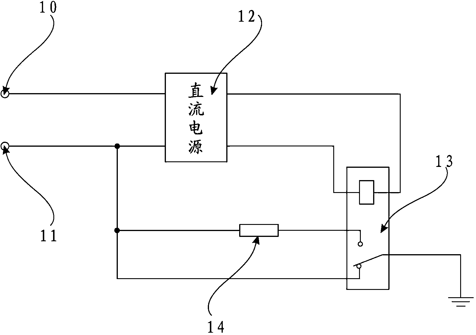
[0026] In order to express the present invention more clearly, the present invention will be further described below in conjunction with the accompanying drawings.

[0027] see figure 1 , the solar cell grounding device of the present invention includes a photovoltaic module DC output positive pole 10, a photovoltaic module DC output negative pole 11, a DC power supply 12, a relay 13 and a grounding resistor 14; the DC power supply 12 has a first input terminal, a second input terminal, a second An output terminal and a second output terminal, the relay 13 has an electromagnet, a normally closed contact, a normally open contact and a switch; the photovoltaic module output positive pole 10 is electrically connected to the first input terminal of the DC power supply 12, and the photovoltaic module DC output negative pole 11 It is electrically connected to the second input terminal of the DC power supply 12, and the electromagnet of the relay 13 is electrically connected between ...


PUM


Abstract

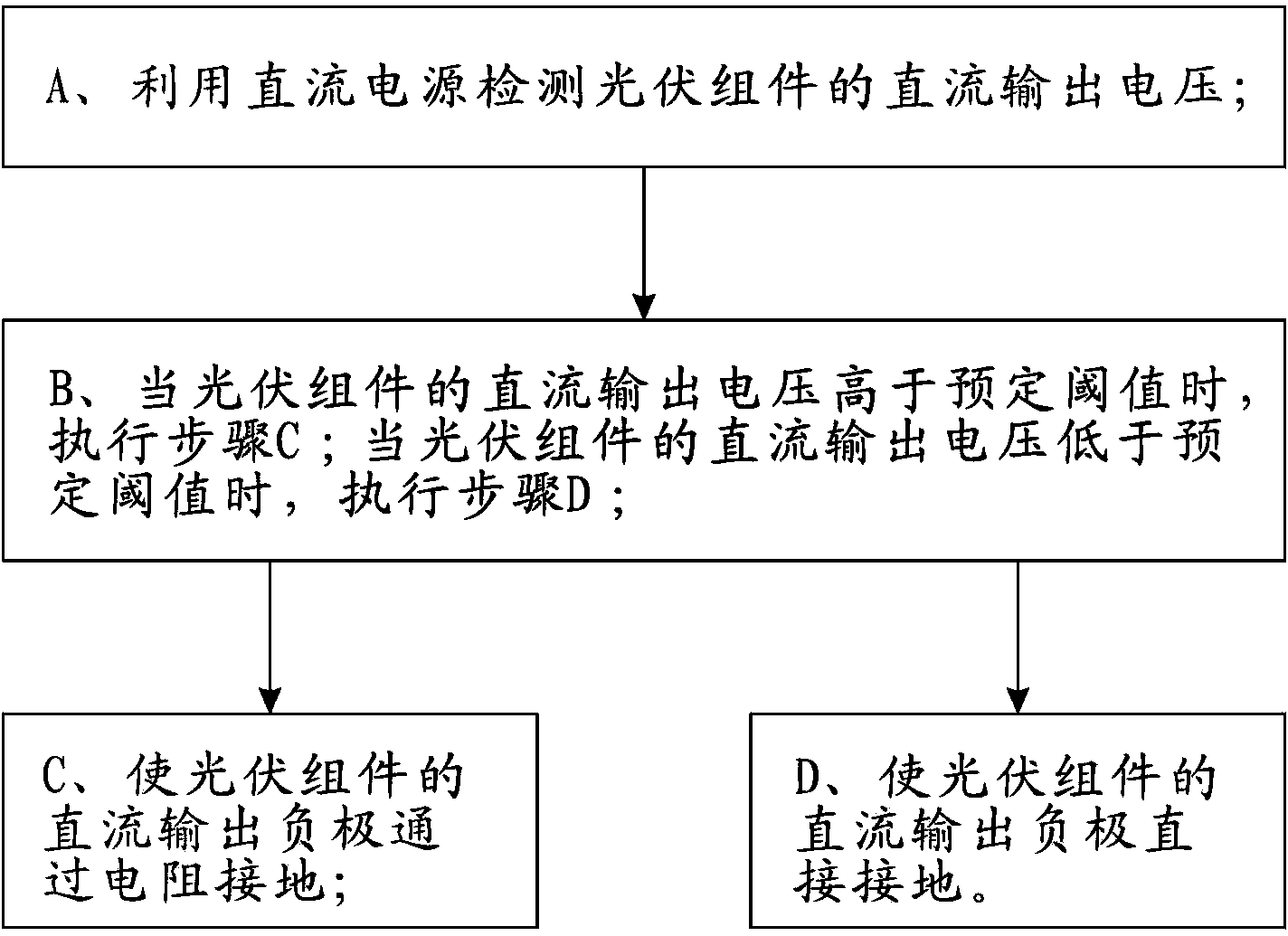
The invention discloses a solar cell grounding device and method. The solar cell grounding method comprises the following steps of A, utilizing a DC (direct current) power supply to detect the DC output voltage of a photovoltaic module; B, carrying out step C when the DC output voltage of the photovoltaic module is higher than a predefined threshold and carrying out step D if the DC output voltage of the photovoltaic module is lower than the predefined threshold; C, enabling the DC output cathode of the photovoltaic module to be grounded through a resistor; D, enabling the DC output cathode of the photovoltaic module to be directly grounded. According to the solar cell grounding device and method, the DC power supply is used for detecting the working state of the photovoltaic module, when the photovoltaic module does not work, the output voltage of the DC power supply cannot make a relay to operate, the DC output cathode of the photovoltaic module is directly grounded, electrostatic charges are eliminated, and attenuation of the photovoltaic module can be avoided. When the photovoltaic module works normally, the output power supply of the DC power supply enables the relay to operate, the DC output cathode of the photovoltaic is grounded through the resistor, and the normal operation of the photovoltaic can be guaranteed.

Description

technical field [0001] The invention relates to the technical field of solar cells, in particular to a solar cell grounding device and method. Background technique [0002] After photovoltaic modules are used for a period of time, the power generation will attenuate to a certain extent, because crystalline silicon modules will have a potential-induced degradation (PID) effect, and thin-film modules will cause damage to the transparent conductive oxide (TCO) layer. If no corrective measures are taken, The power generation of the modules will drop significantly, seriously affecting the revenue of the photovoltaic system. [0003] At present, the industry mainly adopts the method of grounding the negative electrode of the inverter to eliminate the static charge on the components to prevent this from happening. However, this grounding method is not applicable in some occasions due to the different topological structure principles of the inverter, and the cost is relatively high...

Claims


Application Information

Patent Timeline
IPC IPC(8): H02S40/30
CPCY02E10/50
Inventor 刘继茂
Owner 刘继茂
Why Eureka
Eureka Blog
Learn More