A long-life knife gate valve

A long-life, knife-shaped technology, applied to sliding valves, valve devices, engine components, etc., can solve the problems of gate valve damage, seal failure, screwing, etc., and achieve the effect of online maintenance and convenient use

Active Publication Date: 2016-02-17
HUAIBEI XINXIANG HYDRAULIC ELECTROMECHANICAL COMPLETE EQUIP MFG CO LTD
View PDF4 Cites 3 Cited by
  • Summary
  • Abstract
  • Description
  • Claims
  • Application Information

AI Technical Summary

Problems solved by technology

[0002] There are two types of sealing rings in the valve cavity of existing knife gate valves, one is installed in the middle of the valve body, and the other is installed in the sealing groove of the valve seat. These two types of sealing rings are installed during production. In the knife-shaped gate valve, if the seal ring is partially or slightly damaged, the entire valve will fail to seal, and the style of the seal ring directly determines the sealing effect and service life; The motor rotates to move up and down. When the ram enters the interior, it is impossible to confirm whether it is in the end, and it will often be screwed to death. This is also a kind of damage to the sealing ring. Long-term excessive extrusion will cause the seal to fail. At the same time, the ram is pulled out and inserted. During the process, there will be swings, which will squeeze the valve body and sealing ring, resulting in cutting and accelerating the damage of the gate valve
In order to ensure the service life of the knife gate valve and the sealing effect of the gate valve, a reasonable structure is required, but none of the existing knife gate valves discloses such a long-life structure

Method used


Image

  • A long-life knife gate valve
  • A long-life knife gate valve
  • A long-life knife gate valve

Examples


Embodiment Construction

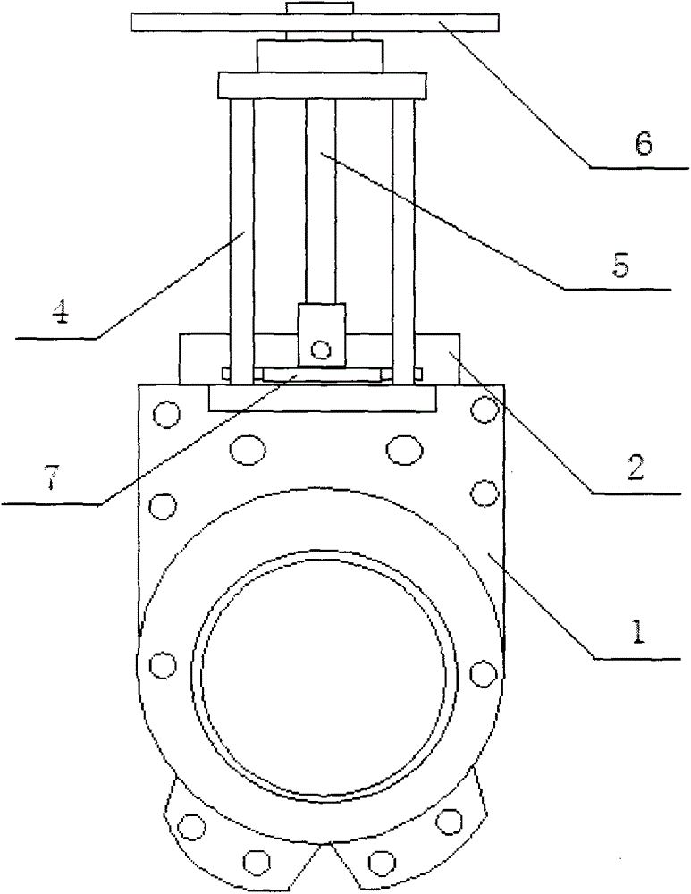
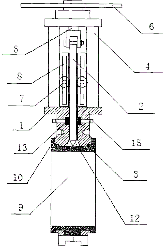
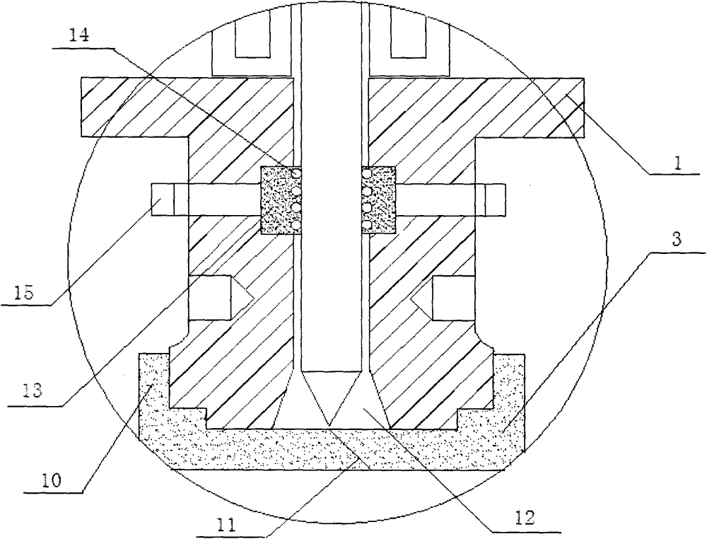
[0016] Such as figure 1 , 2 A long-life knife-shaped gate valve shown in . Support frame 4, valve stem 5, transmission member 6, balance rod 7, valve stem 5 is installed in the middle of support frame 4, its upper end is connected with transmission member 6, and its lower end is connected with gate plate 2, and the support frame 4 is located on both sides of gate plate 2 There is a sliding groove 8, and the two ends of the balance bar 7 are installed in the movable groove 8, and are in rolling contact with the gate plate 2; the gate plate 2 is installed on the valve body 1, and the valve body 1 is divided into a symmetrical front half valve body and the rear half valve body, the upper part of the inner wall of the valve cavity 9 where the front half valve body and the rear half valve body are located is set as a stepped structure, and the lower part is set as a platform structure; the sealing ring 3 is an elastic sealing ring, which is set as two independent rings Body, its ...


PUM


Abstract

The invention discloses a long-life knife gate valve which comprises a valve body, a gate plate and a sealing ring, wherein a support frame, a valve rod, a transmission part and balancing poles are arranged at the upper part of the valve body; sliding chutes are formed in the support frame and located on two edges of the gate plate; two ends of each balancing pole are mounted in the sliding chutes and in rolling contact with the gate plate; the upper part of the inner wall of a valve cavity adopts a step type structure, and the lower part of the inner wall of the valve cavity adopts a platform structure; the sealing ring comprises two independent ring bodies; outer circumferential surfaces of the ring bodies are in interference fit with inner walls of valve cavities of two parts of the valve body to form sealing; an external lug of the sealing ring is located on the outer wall of the valve body; diagonal planes of the two sealing ring bodies at the upper part of the valve cavity are contacted; a V-shaped blade at the lower part of the gate plate is located at the joint of the diagonal planes of the two sealing ring bodies, and a V-shaped groove symmetric to the gate plate is formed in the valve cavity; sealing strips are arranged on the valve body at the upper part of the valve cavity; and cylindrical ribs are arranged on the sealing strips. According to the long-life knife gate valve, the structure design is ingenious, the service life of the gate valve far surpasses that of a conventional gate valve, the use is convenient, and on-line maintenance, overhaul and replacement can be realized.

Description

technical field [0001] The invention relates to a knife-shaped gate valve, in particular to a long-life knife-shaped gate valve. Background technique [0002] There are two types of sealing rings in the valve cavity of existing knife gate valves, one is installed in the middle of the valve body, and the other is installed in the sealing groove of the valve seat. These two types of sealing rings are installed during production. In the knife-shaped gate valve, if the seal ring is partially or slightly damaged, the entire valve will fail to seal, and the style of the seal ring directly determines the sealing effect and service life; The motor rotates to move up and down. When the ram enters the interior, it is impossible to confirm whether it is in the end, and it will often be screwed to death. This is also a kind of damage to the sealing ring. Long-term excessive extrusion will cause the seal to fail. At the same time, the ram is pulled out and inserted. During the process, ...

Claims


Application Information

Patent Timeline
Patent Type & Authority Patents(China)
IPC IPC(8): F16K3/02F16K3/314F16K3/30
CPCF16K3/0227F16K3/0281F16K3/314F16K3/3165
Inventor 陈金龙
Owner HUAIBEI XINXIANG HYDRAULIC ELECTROMECHANICAL COMPLETE EQUIP MFG CO LTD
Why Eureka
Try Eureka