Material bed clearing structure of centrifugal machine

A technology of centrifuge and material layer, which is applied in the direction of centrifuge, etc., and can solve the problems of polluting the materials in the pot, unclean scraping, and affecting the drying of the materials in the pot.

Inactive Publication Date: 2014-03-19
JIANGSU HUADA CENTRIFUGE
View PDF5 Cites 5 Cited by
  • Summary
  • Abstract
  • Description
  • Claims
  • Application Information

AI Technical Summary

Problems solved by technology

When the material layer removal structure of the centrifuge with this material layer removal structure is actually used, for safety reasons, usually the scraper cannot touch the inner wall of the drum when it is working, that is, there is a small distance from the inner wall of the drum. , then there will inevitably be a thin layer on the inner wall of the drum that cannot be scraped off, that is, the scraped material is not clean, which will affect the drying of the raw material or pollute the raw material

Method used


Image

  • Material bed clearing structure of centrifugal machine
  • Material bed clearing structure of centrifugal machine

Examples


Embodiment Construction

[0012] Specific embodiments of the present invention will be described in detail below in conjunction with the accompanying drawings.

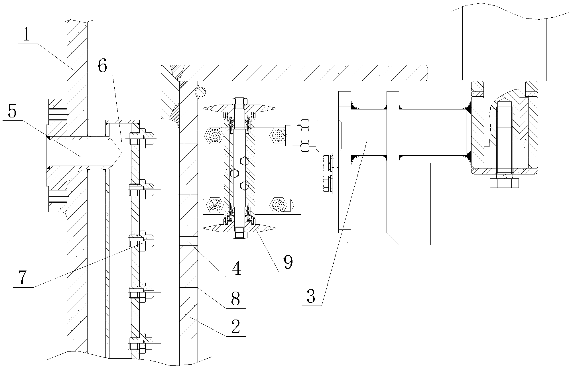
[0013] Such as figure 1 , figure 2 As shown, the material layer removal structure in the centrifuge of the present invention includes a housing 1, a drum 2 arranged in the housing 1 and a scraper 3 arranged in the drum 2, and the wall of the drum 2 is covered with The filter hole 4 is provided with an air blowing device aiming at the filter hole 4 on the housing 1 . In actual production, the blowing device with a simple structure as follows can be used, which includes an air intake pipe 5 passing through the wall of the shell 1, and the end of the air intake pipe 5 located in the shell 1 is connected with an air delivery pipe 6, and the air delivery pipe 6 is provided with a The air blowing nozzle 7 is arranged, and the air blowing nozzle 7 corresponds to the filter hole 4 . During actual production, a filter cloth 8 can also be arranged o...


PUM


Abstract

The invention discloses a material bed clearing structure of a centrifugal machine. The structure is capable of clearing away residual materials on drums and comprises a casing, a drum arranged in the casing and a scraper which is arranged in the drum. Filtering holes are formed in the wall of the drum, and a blower aligning at the filtering holes to perform blowing is arranged on the casing. The structure has the advantages that the blower is used for blowing residual material beds on the inner wall of the drum from the reverse side, so that the residual material beds fall off, and clearing is achieved.

Description

technical field [0001] The invention relates to a material layer removal structure in a centrifuge. Background technique [0002] The existing material bed removal structure of the centrifuge comprises a casing, a rotating drum arranged in the casing and a scraper arranged in the rotating drum. When the material layer removal structure of the centrifuge with this material layer removal structure is actually used, for safety reasons, usually the scraper cannot touch the inner wall of the drum when it is working, that is, there is a small distance from the inner wall of the drum. , then it is bound to produce a thin layer on the inner wall of the drum that cannot be scraped off, that is, the scraped material is not clean, which will affect the drying of the cooked material or pollute the cooked material. Contents of the invention [0003] The technical problem to be solved by the present invention is to provide a material layer removal structure in a centrifuge capable of r...

Claims


Application Information

Patent Timeline
Patent Type & Authority Applications(China)
IPC IPC(8): B04B15/06
Inventor 蔡建春胡振华范匡余王琪
Owner JIANGSU HUADA CENTRIFUGE
Why Eureka
Try Eureka