Stealing hole pressure plugging device of oil pipeline

A technology for oil pipelines and plugging devices, which is applied in the direction of pipe components, pipes/pipe joints/fittings, mechanical equipment, etc., which can solve the problems of large losses, long time required, and unsightly appearance of oil pipeline enterprises, and achieve easy disassembly, assembly, transportation, The land excavation area is small and the sealing effect is good

Inactive Publication Date: 2014-03-12
QINGDAO UNIV OF SCI & TECH
View PDF5 Cites 5 Cited by
  • Summary
  • Abstract
  • Description
  • Claims
  • Application Information

AI Technical Summary

Problems solved by technology

When sealing such stolen holes on oil pipelines, because the pressure of the crude oil in the pipeline is too high, during construction, the crude oil in the pipeline must first be stopped and pressure relieved before the sealing can be carried out. It takes a long time for the pipeline to resume oil delivery. For long-distance oil pipelines, such a blocking method is inefficient and inconvenient for construction. The suspension of oil pipelines has caused huge losses to enterprises.
[0003] At present, there are mainly two methods for sealing the stolen holes of oil pipelines: welding the cover cap on the ball valve and embedding wooden wedges in the stolen holes; The wedge of the pipeline will block the passage of the cleaning ball in the pipeline. The above two methods need to be implemented after the pipeline is stopped and the pressure is relieved. The stoppage of the pipeline will cause huge economic losses to the oil company.

Method used


Image

  • Stealing hole pressure plugging device of oil pipeline
  • Stealing hole pressure plugging device of oil pipeline
  • Stealing hole pressure plugging device of oil pipeline

Examples


Embodiment Construction

[0014] The present invention will be further described in detail in conjunction with the accompanying drawings and specific embodiments

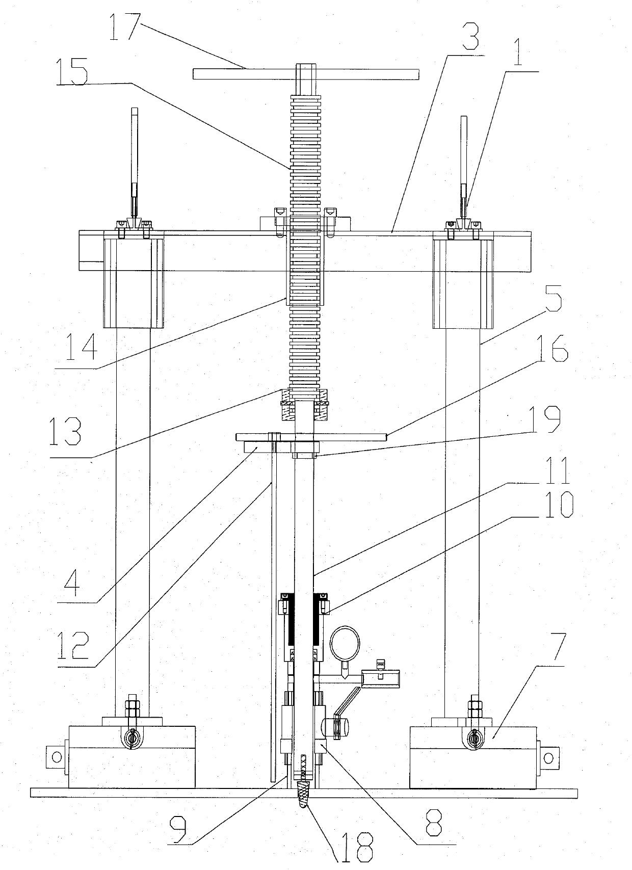
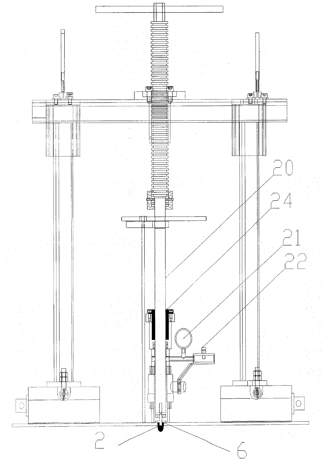
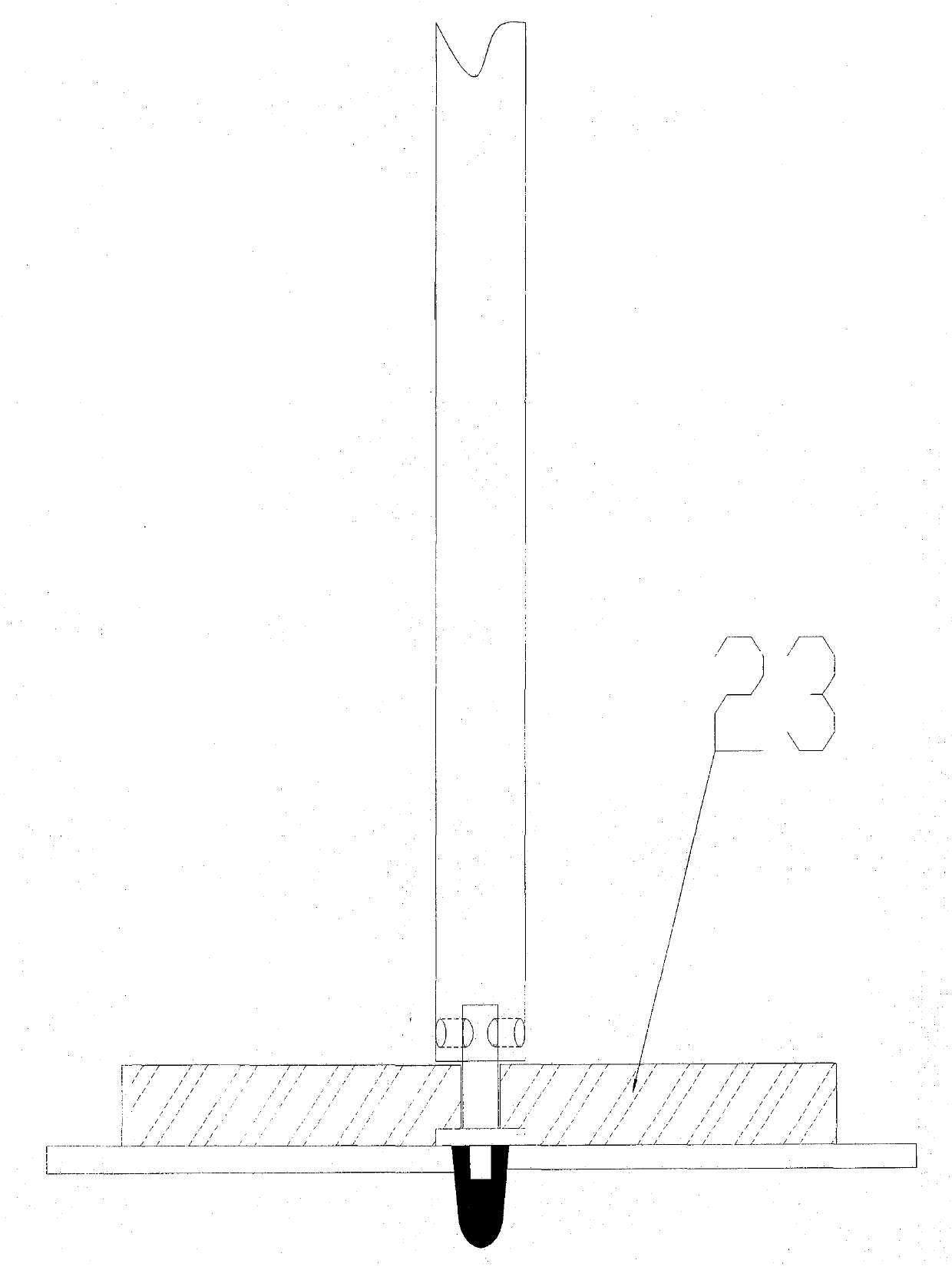
[0015] The oil pipeline theft hole with pressure plugging device of the present invention mainly consists of: a main cylinder 10, a plugging shaft 20, a screw 15, a beam 3, a side column 5, a fixing nut, a retaining ring 13, a metal washer 19, and a plugging shaft 20 , Measuring shaft 11, shaft turning lever 16, screw feed lever 17, needle holder 4, indicator needle 12, magnetic base 7, quick clamp 1, lock nut 14, grinding head 18, plug 6, hydraulic gauge 21 , a pressure relief valve 22, a rubber seal plug 2, a cover plate 23, and a sealing ring 24. It is characterized in that: the magnetic base 7 adopts a magnetic table base with strong adsorption force as the base of the occluder, and the magnetic base 7 After the wrench is pulled down, self-locking can be realized, so that the magnetic base 7 will be adsorbed and fixed on the surface of t...


PUM


Abstract

The invention discloses a stealing hole pressure plugging device of an oil pipeline. The stealing hole pressure plugging device of the oil pipeline is mainly composed of a rapid clamp, a rubber plug, a beam, a needle frame, a side upright, a plug, a magnetic base, a main cylinder, a diameter measuring shaft, a pointer, a check ring, a locknut, a screw rod, an axial rotary lever, a screw rod feeding lever, a grinding head, a metal gasket, a plugging shaft, a hydraulic meter, a pressure release valve and a cover board. The magnetic base is attracted to the oil pipeline. The side upright is fixed to the magnetic base. The beam is pressed tightly by the rapid clamp and fixed to the upper end of the side upright. The screw rod penetrates through the locknut on the beam and presses the diameter measuring shaft or the plugging shaft tightly. The diameter of a stealing hole is measured through the grinding head at the lower end of the diameter measuring shaft. The stealing hole is plugged through the plug and the rubber plug at the lower end of the plugging shaft. After a short tube is cut off, the plugs are tightly pressed through the cover board and are welded. According to the stealing hole pressure plugging device of the oil pipeline, on the premise that the oil pipeline is under pressure and delivery is not stopped, the diameter of the stealing hole is measured, the stealing hole is plugged, the whole process is conducted in a sealed mode, crude oil is not leaked, the structure is simple, use is safe and convenient, and economic loss caused by a delivery stop of the oil in the oil pipeline is avoided.

Description

technical field [0001] The invention relates to a sealing device for an oil pipeline, in particular to a pressure sealing device for oil pipeline burglary hole sealing without leakage when the oil pipeline is in a state of non-stop delivery. Background technique [0002] Oil pipeline is an important means of oil transportation, and its safety is related to the lifeline of the national economy. At present, it is common for lawbreakers to drill holes in oil pipelines and install ball valves to steal oil. Through ball valves, oil can be repeatedly stolen. When sealing such stolen holes on oil pipelines, because the pressure of the crude oil in the pipeline is too high, during construction, the crude oil in the pipeline must first be stopped and pressure relieved before the sealing can be carried out. It takes a long time for the pipeline to resume oil delivery. For long-distance oil pipelines, such a blocking method is inefficient and inconvenient for construction. The suspens...

Claims


Application Information

Patent Timeline
IPC IPC(8): F16L55/168
CPCF16L55/168
Inventor 黄翼虎刘文龙徐俊马吉祥林其安王新龙
Owner QINGDAO UNIV OF SCI & TECH
Why Eureka
Try Eureka