Hole-channel-staggering-type high-performance metal honeycomb carrier
A metal honeycomb carrier, high-performance technology, applied in the direction of catalyst carrier, mechanical equipment, engine components, etc., can solve the problem of uneven air distribution of metal honeycomb carrier, improve conversion efficiency and utilization rate, low air resistance, and ingenious structural design Effect
Inactive Publication Date: 2014-03-12
黄小春
View PDF4 Cites 5 Cited by
- Summary
- Abstract
- Description
- Claims
- Application Information
AI Technical Summary
Problems solved by technology
[0003] The object of the present invention is to provide a high-performance metal honeycomb carrier with staggered channels, which can effectively improve the uneven air distribution of the traditional flat + corrugated plate metal honeycomb carrier technical flaw
Method used
View moreImage
Smart ImageViewing Examples
Examples
Embodiment Construction
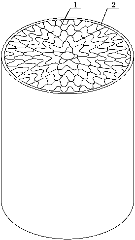
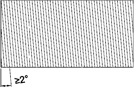
[0011] Referring to the accompanying drawings, a staggered high-performance metal honeycomb carrier made only of corrugated plate rolls, including the use of at least one layer of corrugated plates 1 with an inclination angle ≥ 2°, and the angles are staggered to form concentric circles (spiral) or S Type honeycomb inner core, the outer ring is fixed by a metal shell 2, and the whole is formed by brazing as a metal honeycomb carrier.
Login to View More PUM
 Abstract
The invention discloses a hole-channel-staggering-type high-performance metal honeycomb carrier which is characterized in that the metal honeycomb carrier is made only by corrugated plates in a coiling mode, a traditional structure of flat plates and corrugated plates is broken through, holes and channels are communicated in a staggering mode, a single straight-through hole-channel structure which is not communicated is avoided, design is ingenious, so that the flat plates are avoided, only the corrugated plates are used for making an inner core, and the using number of metal foil belt materials is saved by more than 35%. The metal honeycomb carrier of the novel structure is low in air resistance and even in air flow distribution, the problems that traditional flat plate and corrugated plate metal honeycomb carrier inner core air flow distribution is not even, and the catalyst using rate is not sufficient are solved, and the metal honeycomb carrier is suitable for tail gas purifying catalyst coating of engines for various purposes.
Description
technical field [0001] The invention mainly relates to a metal carrier of a catalytic converter, in particular to a high-performance metal honeycomb carrier with staggered channels made by only using corrugated plate coils. Background technique [0002] A catalytic converter is an engine exhaust purification device that purifies carbon monoxide (CO), hydrocarbons (HC) and nitrogen oxides (NO X ). The exterior of the catalytic converter is a stainless steel shell, and the interior is a metal honeycomb core. In the prior art, the inner core shapes of metal honeycomb carriers mainly include concentric circle (spiral) type and S-type. The inner core structure is made of several flat plates + corrugated plates. The channels of the inner core are not connected to each other. When the engine exhaust gas passes through the metal honeycomb inner core, the airflow spreads from the center to the surroundings, and the flow rate decreases from the center to the outside. The non-interco...
Claims
Login to View More Application Information
Patent Timeline
 IPC IPC(8): F01N3/28B01J32/00
Inventor 黄小春
Owner 黄小春
Features
- R&D
- Intellectual Property
- Life Sciences
- Materials
- Tech Scout
- Unparalleled Data Quality
- Higher Quality Content
- 60% Fewer Hallucinations
Learn More Browse by: Latest US Patents, China's latest patents, Technical Efficacy Thesaurus, Application Domain, Technology Topic, Popular Technical Reports.
© 2025 PatSnap. All rights reserved.Legal|Privacy policy|Modern Slavery Act Transparency Statement|Sitemap|About US| Contact US: help@patsnap.com


