
Unpowered hood

A hood and power technology, applied in the field of unpowered hoods, can solve the problems of short service life, inability to turn off heat preservation, large ventilation resistance coefficient, etc., and achieve the effects of easy application and popularization, reduction of heat loss, and simple manufacturing process.

Active Publication Date: 2014-03-12
锦州鹏翔电力轻钢设备有限公司
View PDF6 Cites 6 Cited by
  • Summary
  • Abstract
  • Description
  • Claims
  • Application Information

AI Technical Summary

Problems solved by technology

Mainly include: 1. The rotation of the hood gives people the illusion of power ventilation. In fact, the product is still a natural ventilation device that does not shelter from the wind. The ventilation is greatly affected by natural factors. The effective ventilation area of ​​the rotating non-powered hood is small and the ventilation resistance coefficient is large. The ventilation capacity of the product is low; 2. Long-term continuous rotation will inevitably cause motion damage, and the service life is short; 3. The combination of the product and the roof installation often causes leakage; 4. The product cannot be closed for heat preservation
[0003] The technical problems of the above-mentioned products lead to insufficient ventilation of many application buildings, and the internal environment of the building cannot meet the ventilation requirements. The movement damage and frequent leakage make the users have to carry out roof renovation, which causes great economic losses to the enterprise.

Method used


Image

  • Unpowered hood
  • Unpowered hood

Examples


Embodiment Construction

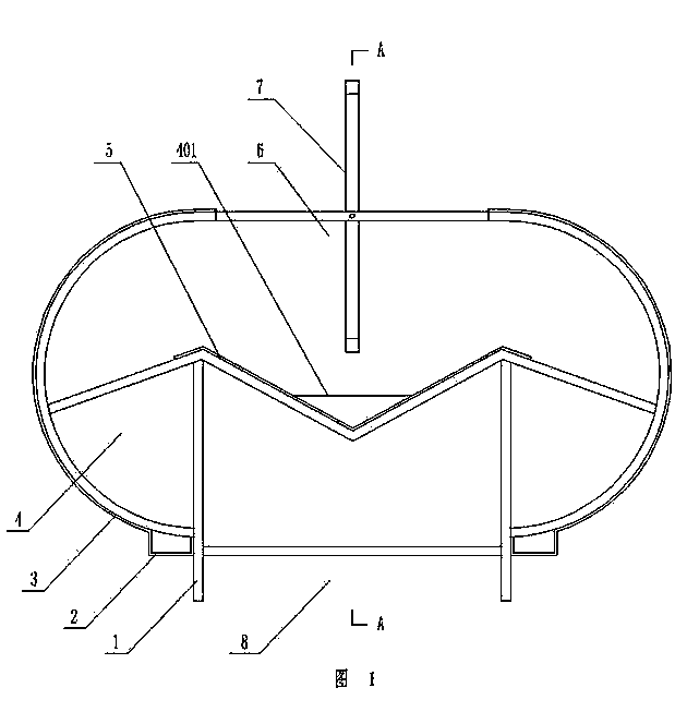
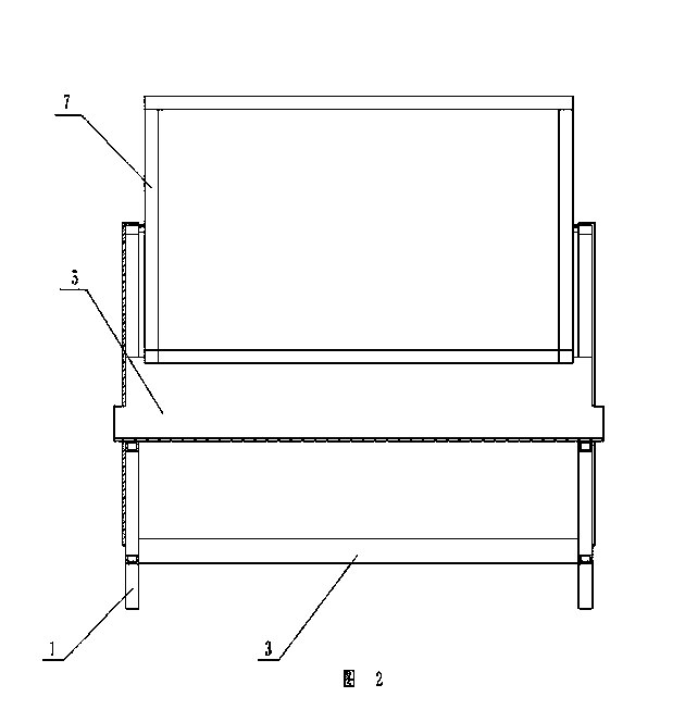
[0012] As shown in the figure, the unpowered hood has a structural support 1, and an arc-shaped outer guard plate 3 is symmetrically fixed on both sides of the structural support 1, and a water ditch 2 is arranged at the bottom of the outer guard plate 3 on both sides of the structural support 1 , The ditch 2 is integrated with the outer guard plate 3 for easy installation. The front and rear ends of the structural support 1 are respectively fixed with end plates 4, and the bottom and upper ends of the structural support 1 are located between the outer guard plates 3 on both sides to form an air inlet 8 and an air exhaust port 6 respectively. A V-shaped rain shield 5 with a width larger than the air inlet 8 and the air exhaust outlet 6 is fixed in the inner middle. Rain plate 5 is led out and is provided with water outlet 401, is hinged with the wind shield 7 that air outlet 6 can be closed at structural support 1 upper end, and the hinge shaft of wind shield 7 is positioned a...


PUM


Abstract

An unpowered hood comprises a structure support. The two sides of the structure support are respectively provided with an arc-shaped outer protecting plate and a ditch in a symmetric mode, and the two ends of the structure support are provided with end plates. An air inlet and an air outlet are formed between the outer protecting plates on the two sides in the bottom and the upper end of the structure support respectively. The unpowered hood is characterized in that a V-shaped rain sheltering plate with the width being larger than that of the air inlet and that of the air outlet is arranged in the middle inside the structure support, the two ends of the V-shaped rain sheltering plate are led out from the end plates respectively, water discharging openings are formed in the positions, corresponding to the leading-out portions of the V-shaped rain blocking plate, of the end plates, and a wind sheltering plate which can be used for closing the air outlet is hinged to the upper end of the structure support. The unpowered hood has the advantages that the effective ventilation area is large, the ventilation effect is good, weather variations do not have to be worried during ventilation, and product ventilation is not affected by outside wind; movement abrasion is small, and the service life is long; the air outlet can be closed through the wind sheltering plate, building ventilation heat loss is reduced, and rain and snow backward flowing due to the weather variations does not have to be worried; manufacturing process is simple, construction cost is low, and application and popularization are easy.

Description

technical field [0001] The invention relates to a natural ventilation device, in particular to a non-powered wind cap. Background technique [0002] As a small single-unit ventilation product, rotating non-powered hoods are mostly used in architectural applications. With the popularity of this product, the product has highlighted various application technical problems. Mainly include: 1. The rotation of the hood gives people the illusion of power ventilation. In fact, the product is still a natural ventilation device that does not shelter from the wind. The ventilation is greatly affected by natural factors. The effective ventilation area of ​​the rotating non-powered hood is small and the ventilation resistance coefficient is large. The ventilation capacity of the product is low; 2. Long-term continuous rotation will inevitably cause motion damage, and the service life is short; 3. The combination of the product and the roof installation often causes leakage; 4. The produc...

Claims


Application Information

Patent Timeline
Patent Type & Authority Applications(China)
IPC IPC(8): E04F17/04
CPCF24F7/02F24F13/14F24F2013/1453
Inventor 单晓晴韦福利杨丽萍卢彤彤杨立年单连勤
Owner 锦州鹏翔电力轻钢设备有限公司
Learn More