
Special equipment for deburring of hub valve hole

A special equipment, valve hole technology, applied in the directions of transportation, packaging, vehicle parts, etc., can solve the problems of high labor intensity, different proficiency, low deburring efficiency, etc., and achieve the effect of reducing labor intensity, stable quality and improving efficiency.

Active Publication Date: 2014-03-12
ZHEJIANG JINGU CO LTD
View PDF6 Cites 15 Cited by
  • Summary
  • Abstract
  • Description
  • Claims
  • Application Information

AI Technical Summary

Problems solved by technology

[0004] The object of the present invention is to overcome the problems of low deburring efficiency and high labor intensity in the deburring operation of the wheel hub valve hole in the prior art; and the problem of unstable deburring quality due to different proficiency of workers, to provide a method that can It is a special equipment for deburring hub valve holes that effectively improves deburring efficiency, reduces labor intensity, and ensures stable deburring quality

Method used


Image

  • Special equipment for deburring of hub valve hole
  • Special equipment for deburring of hub valve hole
  • Special equipment for deburring of hub valve hole

Examples


Embodiment Construction

[0026] Below in conjunction with accompanying drawing and specific embodiment the present invention is described in further detail:

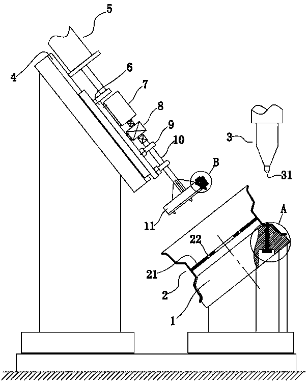
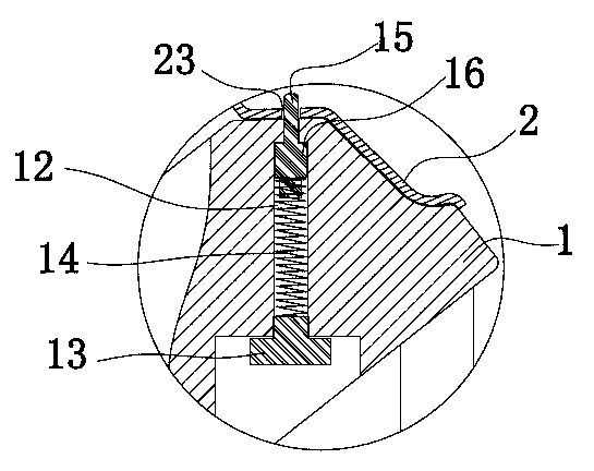
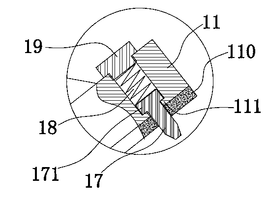
[0027] Such as figure 1 , figure 2 As shown, a special equipment for deburring the valve hole of a wheel hub, including a machine table, an annular lower die table 1 arranged on the machine table and matched with the inner peripheral surface of the wheel hub 2, and a punch 3 located above the annular lower die table. A vertical hole 12 corresponding to the valve hole 23 of the wheel hub 2 is provided on the outer peripheral surface of the annular lower mold table 1 . The angle between the centerline of the vertical hole 12 and the centerline of the annular lower mold table 1 is the same as the angle between the axis of the hub 2 and the centerline of the valve hole 23 . The vertical holes 12 are arranged vertically. The vertical hole 12 is a stepped through hole with a circular cross-section, and the cross-sectional area of ​​the stepped thr...


PUM


Abstract

The invention discloses special equipment for deburring of a hub valve hole. The special equipment can effectively improve deburring efficiency, reduce labor intensity and guarantee stable deburring quality. The special equipment comprises a machine table, an annular lower die table and a punch, wherein the annular lower die table is arranged on the machine table and matched with the inner peripheral face of a hub, and the punch is located above the annular lower die table. The outer peripheral face of the annular flow die table is provided with a vertical hole corresponding to the hub valve hole, and the included angle between the center line of the vertical hole and the center line of the annular lower die table is the same as that between the axis of the hub and the center line of the valve hole. An alignment ejector pin capable of moving upward and downward and a first reset spring located below the alignment ejector pin and used for ejecting the alignment ejector pin are disposed in the vertical hole. The punch is located over the alignment ejector pin.

Description

technical field [0001] The invention relates to a deburring device, in particular to a special device for deburring a hub valve hole. Background technique [0002] During the manufacturing process of the automobile wheel hub, a valve hole needs to be punched out on the rim of the wheel hub. The blanking process inevitably produces burrs on the edge of the valve hole; therefore, a deburring process is required after the valve hole is punched and formed. At present, the deburring process of the valve hole of the wheel hub usually uses an electric drill or a manual drill; when deburring, the operator holds the drill and adopts the method of manually drilling the burr with the drill to remove the burrs on the edge of the valve hole. For example, Chinese Patent Publication No. CN1843675, date of publication on October 11, 2006, is a quick manual cleaning tool for orifice burrs, in which there is a bowed crank with a rotatable crank short pipe in the middle, and the top of the cra...

Claims


Application Information

Patent Timeline
Patent Type & Authority Applications(China)
IPC IPC(8): B21D53/88B21D19/00
Inventor 孙锋峰孙炼飞孙兴源赵尊一章华
Owner ZHEJIANG JINGU CO LTD
Learn More