
Piston swing cylinder hydraulic motor

A technology of hydraulic motor and plunger, applied in the field of plunger type swing cylinder hydraulic motor, can solve the problems of large contact stress, unstable tilting force and large lateral force of the working part, so as to improve the mechanical efficiency and volumetric efficiency, ensure the Low-speed performance to ensure stable results

Active Publication Date: 2016-01-13
宁波欧易液压有限公司
View PDF5 Cites 5 Cited by
  • Summary
  • Abstract
  • Description
  • Claims
  • Application Information

AI Technical Summary

Problems solved by technology

The latter has the defects of complex structure, large contact stress of the working part, large lateral force, short life and high processing cost. On the other hand, when the inner curve motor is working, it needs back pressure, which reduces the working efficiency.
[0003] In particular, the structure of the plunger-connecting rod assembly used in the connecting rod hydraulic motor has the disadvantages of large joint surface between the connecting rod and the crankshaft, which is not easy to process, and it is easy to cause leakage between the joint surface during the working process, which will cause friction The force between the pairs is too large, easy to wear, and the service life is short
At the same time, when the connecting rod swings, there is an unstable tilting force between the plunger cylinder and the plunger, which is prone to wear, which eventually reduces the volumetric efficiency and mechanical efficiency, and affects the stability at low speeds

Method used


Image

  • Piston swing cylinder hydraulic motor
  • Piston swing cylinder hydraulic motor
  • Piston swing cylinder hydraulic motor

Examples


Embodiment Construction

[0028] The present invention will be further described in detail below in conjunction with the accompanying drawings and embodiments.

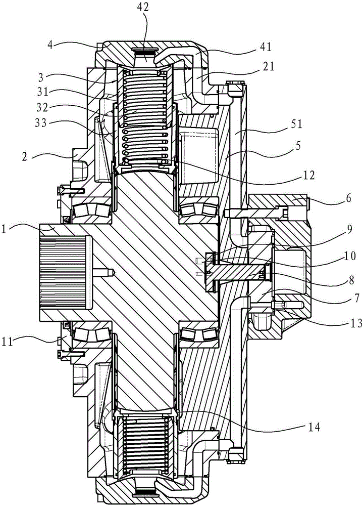
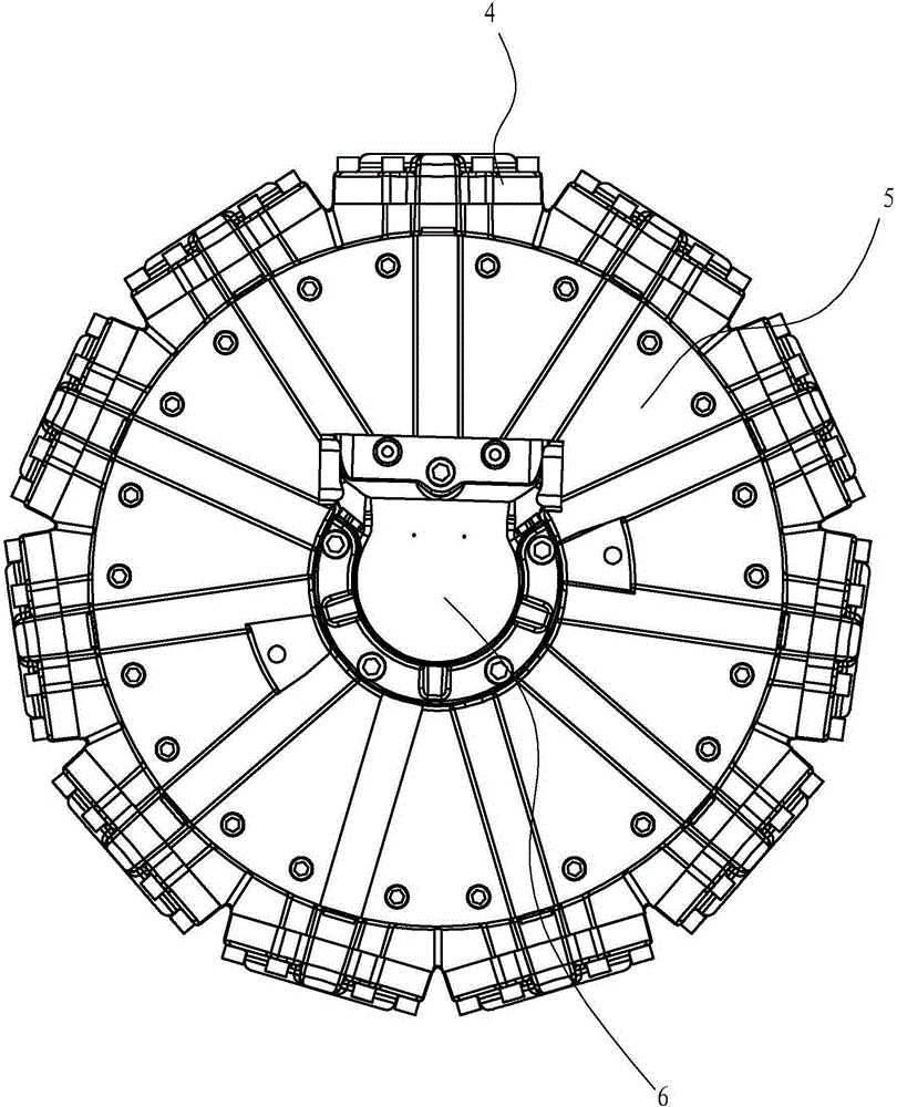
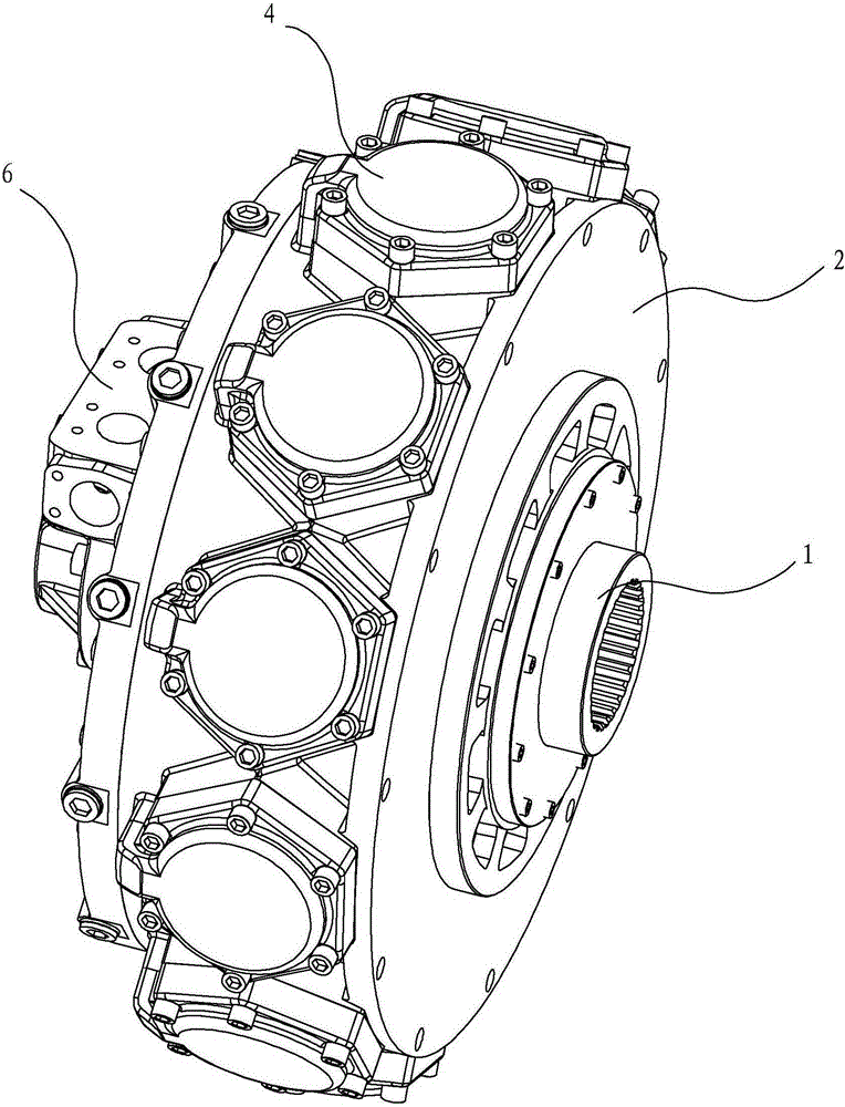
[0029] Such as Figure 1-14 As shown, the plunger swing cylinder hydraulic motor of the present invention includes a casing composed of a casing 2 and a front end cover 11 and a rear end cover 5 arranged on the front end surface and the rear end surface of the casing 2, and is arranged on the peripheral surface of the casing. The upper cylinder head 4, the eccentric shaft 1 supported in the casing by a set of bearings, and the oil distribution mechanism arranged on the rear end cover 5 are arranged radially along the radial direction of the eccentric shaft 1 in the casing. One above-mentioned cylinder cover 4, each cylinder cover 4 is provided with a piston-cylinder assembly 3, and each piston-cylinder assembly 3 includes a hollow piston 31 sliding in the inner cavity of the hollow oil cylinder 33 and a piston placed in the inner cavity of the...


PUM


Abstract

The invention discloses a hydraulic motor with plungers and swinging cylinders. The hydraulic motor is characterized in that odd-numbered piston-oil cylinder components are radially arranged along the radial circumferential direction of an eccentric shaft in an outer shell; each piston-oil cylinder component comprises a hollow plunger, which slides in the inner cavity of a hollow oil cylinder and a spring, which is arranged in the inner cavity of each oil cylinder; each oil cylinder is limited on the eccentric shaft by a retaining ring; the opposite contact surface of each oil cylinder and the eccentric shaft and the opposite contact surface of each piston and a cylinder lid are designed to be spherical surfaces; the two ends of the spring are butted with each piston and each oil cylinder respectively, so that the opposite spherical surface of each oil cylinder and the eccentric shaft and the opposite spherical surface of each piston and the cylinder lid are in tight fit. The pressure generated by the high pressure oil in each oil cylinder directly acts on the opposite spherical surface of the cylinder lid and the eccentric shaft, each piston and each oil cylinder can carry out self-alignment and radial force is not generated, thus the abrasion of the hydraulic motor is reduced and the machine efficiency and the volume efficiency of the hydraulic motor are increased, especially the number of the cylinders is increased to 11 and the displacement and the torque of the hydraulic motor are greatly improved.

Description

technical field [0001] The invention relates to a hydraulic motor, in particular to a plunger type swing cylinder hydraulic motor. Background technique [0002] At present, hydraulic motors have been widely used in various engineering fields, and with the development of technology, the demand for low-speed, high-torque, and large-displacement hydraulic motors is increasing. And so far, hydraulic motors with low speed, high torque, and large displacement mostly use connecting rod hydraulic motors, such as the connecting rod single-acting 18 plunger cylinder disclosed in "A Kind of Hydraulic Motor" with the Chinese patent authorization announcement number CN202789314U double row radial motor. There are also multi-acting internal curve motors. However, the former hydraulic motor has a large outline size and a large pressure and flow pulsation. The latter has the defects of complex structure, large contact stress in the working part, large lateral force, short life and high p...

Claims


Application Information

Patent Timeline
Patent Type & Authority Patents(China)
IPC IPC(8): F03C1/053F03C1/38
Inventor 朱小化
Owner 宁波欧易液压有限公司
Learn More