Automatic fruit-picking and leave-removing device
A technology of automatic and buffer devices, applied in the direction of picking machines, agricultural machinery and implements, etc., can solve the problems of high cost and low picking efficiency, and achieve the effects of ensuring quality, saving picking costs, and improving picking efficiency
- Summary
- Abstract
- Description
- Claims
- Application Information
AI Technical Summary
Problems solved by technology
Method used
Image
Examples
Embodiment 1
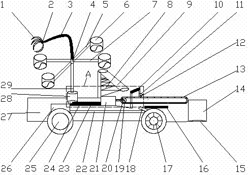
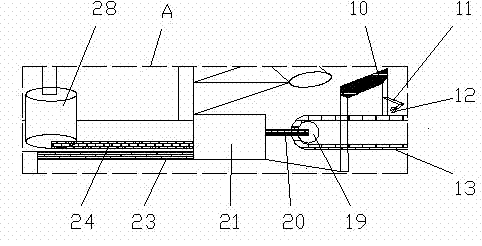
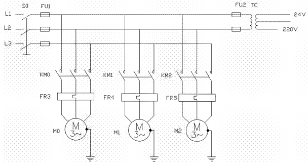
[0022] Embodiment 1: as Figure 1-4 As shown, an automatic fruit-picking and leaf-removing device includes a manipulator 1, a monitoring scanner 2, a manipulator I3, a rotating fulcrum 4, a rotating shaft 5, a receiver 6, an opening and closing valve 7, a shock absorber I8, a buffer device 9, Image processing device 10, mechanical arm II 11, leaf shears 12, conveyor belt 13, container 14, fuel tank 16, brake 17, shock absorber II 18, drive motor I 19, relay I 20, PLC 21, drive shaft 22, relay II 23, relay III 24, Wheel 25, drive motor II 26, car body 27, drive motor III 28, support rod 29; wherein the manipulator 1 is located at one end of the manipulator Ⅰ3, the monitoring scanner 2 is attached to the manipulator 1, and the manipulator 13 is located above the rotation fulcrum 4, rotating The fulcrum 4 is located at the center of the rotating shaft 5, the center of the rotating shaft 5 is connected with the support rod 29 through the rotating fulcrum 4, the receiver 6 is locat...
Embodiment 2
[0026] Embodiment 2: as Figure 1-4As shown, an automatic fruit-picking and leaf-removing device includes a manipulator 1, a monitoring scanner 2, a manipulator I3, a rotating fulcrum 4, a rotating shaft 5, a receiver 6, an opening and closing valve 7, a shock absorber I8, a buffer device 9, Image processing device 10, mechanical arm II 11, leaf shears 12, conveyor belt 13, container 14, fuel tank 16, brake 17, shock absorber II 18, drive motor I 19, relay I 20, PLC 21, drive shaft 22, relay II 23, relay III 24, Wheel 25, drive motor II 26, car body 27, drive motor III 28, support rod 29; wherein the manipulator 1 is located at one end of the manipulator Ⅰ3, the monitoring scanner 2 is attached to the manipulator 1, and the manipulator 13 is located above the rotation fulcrum 4, rotating The fulcrum 4 is located at the center of the rotating shaft 5, the center of the rotating shaft 5 is connected with the support rod 29 through the rotating fulcrum 4, the receiver 6 is locate...
PUM
 Abstract
Description
Claims
Application Information
 - R&D Engineer
- R&D Manager
- IP Professional
- Industry Leading Data Capabilities
- Powerful AI technology
- Patent DNA Extraction
Browse by: Latest US Patents, China's latest patents, Technical Efficacy Thesaurus, Application Domain, Technology Topic, Popular Technical Reports.
© 2024 PatSnap. All rights reserved.Legal|Privacy policy|Modern Slavery Act Transparency Statement|Sitemap|About US| Contact US: help@patsnap.com


