Eureka AIR delivers breakthrough ideas for toughest innovation challenges, trusted by R&D personnel around the world.

Two-degree-of-freedom plane translational parallel mechanism with passive hinges to be spherical hinges

A degree of freedom, spherical hinge technology, used in manipulators, program-controlled manipulators, metal processing mechanical parts, etc., can solve the problems of insufficient mechanical properties, low stiffness and dynamic performance, and achieve the effect of good stiffness

Active Publication Date: 2014-02-26
NANJING UNIV OF SCI & TECH
View PDF13 Cites 3 Cited by
  • Summary
  • Abstract
  • Description
  • Claims
  • Application Information

AI Technical Summary

Problems solved by technology

[0004] The present invention proposes a two-degree-of-freedom plane-translation parallel mechanism in order to solve the problems of insufficient mechanical properties of moving component materials, low stiffness and low dynamic performance existing in the existing two-degree-of-freedom plane translation parallel mechanism

Method used


Image

  • Two-degree-of-freedom plane translational parallel mechanism with passive hinges to be spherical hinges
  • Two-degree-of-freedom plane translational parallel mechanism with passive hinges to be spherical hinges
  • Two-degree-of-freedom plane translational parallel mechanism with passive hinges to be spherical hinges

Examples


Embodiment 1

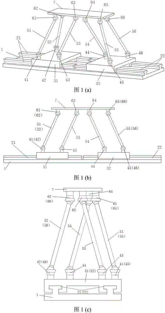
[0030] combine figure 1 (a), the structure of this embodiment includes a fixed platform 1, a first set of parallel guide rails 21 and a second set of parallel guide rails 22 arranged on the fixed platform 1, and the axes of the first set of parallel guide rails 21 and the second set of parallel guide rails 22 coincide;

[0031] The first moving slider 31 arranged on the first group of parallel guide rails 21 and the second moving slider 32 arranged on the second group of parallel guide rails 22, the moving platform 7;

[0032] The first fixed-length connecting rod 51, the second fixed-length connecting rod 52, the third fixed-length connecting rod 53 connected in parallel between the first motion slider 31 and the motion platform 7, the first fixed-length connecting rod 51, the second fixed-length connecting rod The fixed-length connecting rod 52, the third fixed-length connecting rod 53 and the first moving slider 31 are respectively connected by passive ball hinges 41, 42, ...

Embodiment 2

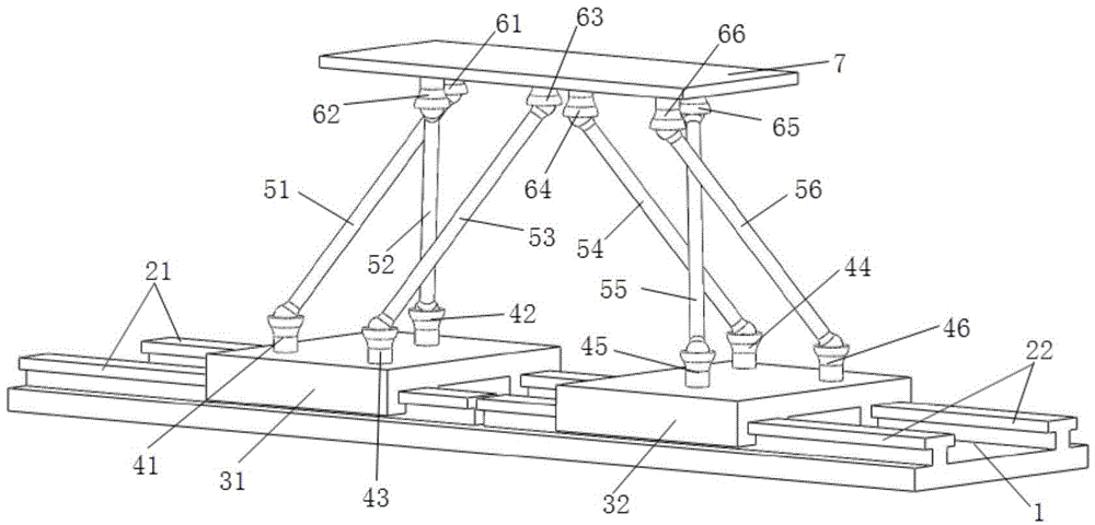
[0041] The structure of this embodiment is as figure 2 As shown, the difference between this embodiment and Embodiment 1 is that the axes of the first group of parallel guide rails 21 and the axes of the second group of parallel guide rails 22 are arranged parallel to each other, so the first moving slider 31 and the second moving slider 32 The directions of motion are parallel to each other.

Embodiment 3

[0043] The structure of this embodiment is as image 3 As shown, the difference between this embodiment and Embodiment 1 is that the projection points of the centers of the passive ball joints 61, 62, 63 on the vertical plane where the axes of the first group of parallel guide rails 21 and the second group of parallel guide rails 22 are located are three points, The projection points of the centers of the passive spherical hinges 64, 65, 66 on the vertical plane where the axes of the first group of parallel guide rails 21 and the second group of parallel guide rails 22 are located are three points, and the first fixed-length connecting rod 51 and the second fixed-length connecting rod 52. The projection lines of the third fixed-length connecting rod 53 on the plane perpendicular to the axes of the first group of parallel guide rails 21 and the second group of parallel guide rails 22 intersect, the fourth fixed-length connecting rod 54, the fifth fixed-length connecting rod 55, ...


PUM


Abstract

The invention provides a two-degree-of-freedom plane translational parallel mechanism with passive hinges to be spherical hinges. The mechanism comprises a first-group parallel guide rail, a second-group parallel guide rail, a first moving slider, a second moving slider and a moving platform, the first-group parallel guide rail and the second-group parallel guide rail are arranged on a fixing platform, the first moving slider is arranged on the first-group parallel guide rail, a second moving slider is arranged on the second-group parallel guide rail, at least six fixed-length connecting rods are parallelly connected between the moving platform and the first moving slider as well as the second moving slider through the passive spherical hinges, the first moving slider and the second moving slider are driving sliders, and at least two fixed-length connecting rods are parallelly connected between the moving platform and the second moving slider. Mechanical performance of a connecting rod component can be brought into full play, and the two-degree-of-freedom plane translational parallel mechanism has good rigidity in a direction perpendicular to a moving plane.

Description

technical field [0001] The invention belongs to the field of parallel robots, in particular to a two-degree-of-freedom plane translation parallel mechanism whose passive hinge is a spherical hinge. Background technique [0002] A parallel mechanism is a mechanism system that connects multiple moving components in parallel between a moving platform and a fixed platform. Because its moving components are connected in parallel, generally speaking, the parallel mechanism has higher stiffness and better dynamic performance than the series mechanism. Therefore, parallel mechanisms are widely used in flight simulators, machine tools, earthquake simulators and other fields with large loads and high dynamic performance requirements. Two-degree-of-freedom planar-translational parallel mechanism is one of the important configurations of parallel mechanisms, and has broad application prospects. [0003] At present, the two-degree-of-freedom plane-translation parallel mechanism, such a...

Claims


Application Information

Patent Timeline
IPC IPC(8): B25J9/00B23Q1/44
Inventor 彭斌彬吴静祝帅胡建宇周宇
Owner NANJING UNIV OF SCI & TECH
Why Eureka
Eureka Blog
Learn More