An emergency hydraulic system of a central hydraulic transmission hydraulic rake thickener
What is Al technical title?
Al technical title is built by PatSnap Al team. It summarizes the technical point description of the patent document.
A hydraulic transmission and hydraulic system technology, applied in the field of hydraulic systems, can solve problems such as wasting resources, polluting the environment, and heavy cleaning workload, and achieve the effects of prolonging service life, timely action, and stable pressure
Inactive Publication Date: 2016-01-20
淮北重科矿山机器有限公司
View PDF7 Cites 0 Cited by
Summary
Abstract
Description
Claims
Application Information
AI Technical Summary
This helps you quickly interpret patents by identifying the three key elements:
Problems solved by technology
Method used
Benefits of technology
Problems solved by technology
At this time, the user needs to clean the concentration tank and remove the material pressed on the scraper before restarting the machine. The workload of cleaning the tank is huge, and it wastes resources and pollutes the environment.
Method used
Image
Click on the blue label to locate the original text in one second.
Reading with bidirectional positioning of images and text.
Examples
Embodiment Construction
[0009] The present invention will be further described below in conjunction with the accompanying drawings.
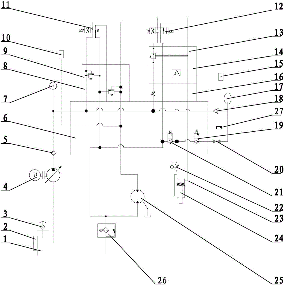
[0010] As shown in the drawings, the present invention includes a hydraulic oil tank 1, an oil temperature level gauge 2, an air filter 3, an oil pump motor unit 4, a pump outlet check valve I5, a hydraulic floor plate 6, a pressure gauge 7, and a low pressure relief valve 8 , high pressure safety valve 9, pressure sensor 10, reversing valve I11, reversing valve II12, pressure reducing valve 13, one-way valve II14, throttle valve 15, pressure detector 16, hydraulic accumulator 17, accumulator inlet One-way valve 18, electric rake electromagnetic ball valve I19, manual stop valve 20, electromagnetic ball valve II21, one-way throttle valve 22, pipeline 23, oil cylinder 24, hydraulic motor 25, oil return filter 26, emergency power supply 27 Wait.
[0011] The hydraulic oil tank 1 for storing hydraulic oil is equipped with an oil temperature level gauge 2, and an air filt...
PUM
Abstract
The invention discloses an emergency hydraulic system of a center hydraulic transmission hydraulic lifting harrow thickener. The series problems caused by power failure of the thickener are solved. The emergency hydraulic system is characterized in that a hydraulic bottom plate block is arranged, a low pressure overflow valve, a high pressure safety valve, a reversing valve I, a throttling valve, a one-way valve II, a pressure reducing valve and a reversing valve II are arranged on the hydraulic bottom plate block, and a hydraulic motor, a one-way throttling valve, an oil cylinder, an electromagnetic ball valve II, an oil return oil filter, an energy accumulator inlet one-way valve, a hydraulic energy accumulator, a pressure detector, a nonelectric lifting harrow electromagnetic ball valve, a manual stop valve, a pressure gauge, a pressure sensor, a nonelectric lifting harrow ball valve connecting emergency power supply and the like are respectively connected through pipelines. According to the emergency hydraulic system of the center hydraulic transmission hydraulic lifting harrow thickener, high pressure oil is stored through the hydraulic energy accumulator, the high pressure oil is released during power failure, and nonelectric automatic harrow lifting is achieved. The emergency power sully is used, so that the nonelectric lifting harrow electromagnetic ball valve is in a normally-closed state and is opened when sudden power failure happens, the nonelectric lifting harrow electromagnetic ball valve is opened by the emergency power supply, the high pressure oil is made to automatically enter an oil cylinder lifting harrow, and the facts that materials press the harrow and a pool is cleared are avoided.
Description
technical field [0001] The invention relates to a hydraulic system of a concentrator, more precisely, it is a hydraulic system of a central hydraulic transmission hydraulic rake concentrator. Background technique [0002] When the thickener is in use, the rotating torque of the scraper rake has a certain range. When the load increases and the rotating torque is greater than the set value, the rake needs to be lifted. Therefore, high-end thickeners are equipped with an automatic rake lifting device. The existing automatic rake lifting systems are all based on normal power supply. However, when the power supply of the power grid is suddenly interrupted during the user’s use, the factory area has no power, all actions of the equipment stop, and the rake lifting system also stops working at the same time. The highest position cannot be mentioned. During the power outage, the gravity settling in the thickening tank did not stop, and the solids suspended in the tank sank to the b...
Claims
Application Information
Patent Timeline
Application Date:The date an application was filed.
Publication Date:The date a patent or application was officially published.
First Publication Date:The earliest publication date of a patent with the same application number.
Issue Date:Publication date of the patent grant document.
PCT Entry Date:The Entry date of PCT National Phase.
Estimated Expiry Date:The statutory expiry date of a patent right according to the Patent Law, and it is the longest term of protection that the patent right can achieve without the termination of the patent right due to other reasons(Term extension factor has been taken into account ).
Invalid Date:Actual expiry date is based on effective date or publication date of legal transaction data of invalid patent.