Eureka AIR delivers breakthrough ideas for toughest innovation challenges, trusted by R&D personnel around the world.

Fluid engine and manufacturing method and application device thereof

An engine and fluid technology, applied in the direction of machines/engines, mechanical power generating mechanisms, mechanical equipment, etc., can solve the problems of incomplete energy conversion, utilization, energy incomplete conversion, utilization, and low energy utilization rate, and achieve a solution The effect of fuel shortage, easy overload protection, and elimination of energy loss

Inactive Publication Date: 2014-02-19
张延友
View PDF0 Cites 0 Cited by
  • Summary
  • Abstract
  • Description
  • Claims
  • Application Information

AI Technical Summary

Problems solved by technology

After they do work, the discharged liquid and gas have a certain amount of energy. If the energy is discharged in vain, this will cause energy loss, that is to say, the energy is not fully converted and utilized, and the energy utilization rate will be low.
[0011] We can call the manufacturing method of the existing power machinery as the manufacturing method of the working medium discharge type. This method will inevitably bring about the shortcomings of the power machinery itself, that is, when the working medium does work, the energy cannot be completely converted and utilized, and the energy utilization rate is low. low, polluting the environment
[0012] Equally, the power mechanical device that utilizes existing power machinery manufacturing method to manufacture also has the deficiency of power machinery itself

Method used


Image

  • Fluid engine and manufacturing method and application device thereof
  • Fluid engine and manufacturing method and application device thereof
  • Fluid engine and manufacturing method and application device thereof

Examples


Embodiment Construction

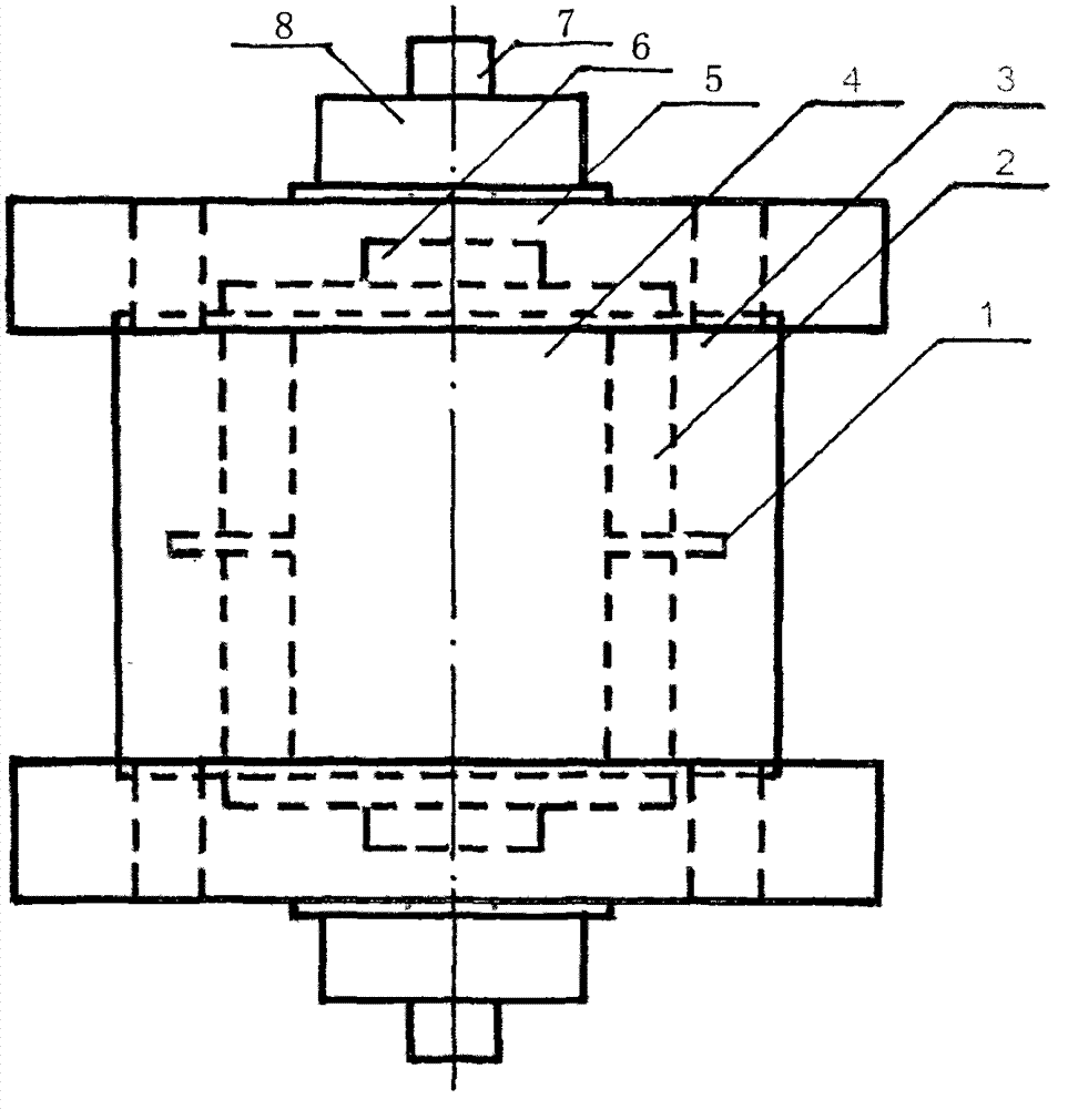
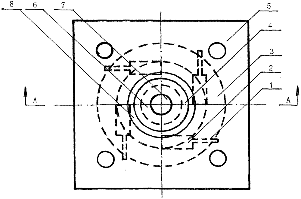
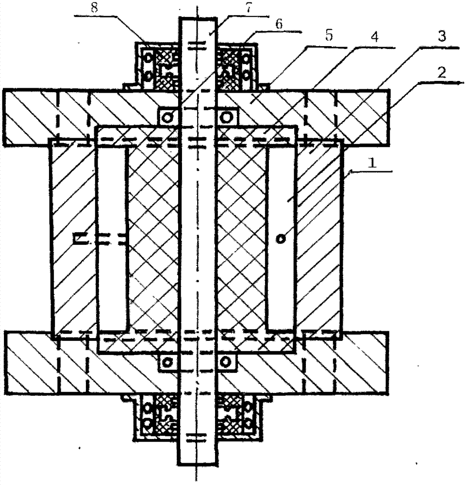
[0043] A volume cavity (2) capable of generating interaction force is formed between the stator (3) and the rotor (4), and the volume cavity (2) is distributed between the stator (3) and the rotor (4) to form a circle. When the working fluid of a certain pressure output by the working fluid adjuster fills the volume chamber (2) through the inlet (1), the stator (3) and the rotor (4) will be staggered, and the first one of the rotor (4) The volume cavity part will form a new volume cavity with the second volume cavity part of the stator (3), and the same misalignment will occur, and so on, and a round of misalignment will result in a circular rotation. Keeping the pressure of the working fluid will make the The engine runs continuously.

[0044] Both ends of the rotor (4) and the stator (3) are respectively provided with end covers (5), and the center of the end cover (5) is equipped with a bearing (6), and the central axis (7) of the rotor (4) is limited by the bearing (6), an...


PUM


Abstract

The invention relates to an engine using fluid as a power source and free of emission, further relates to a manufacturing method and application devices of the engine and aims at solving the problems that energy cannot be converted and utilized and energy utilization efficiency is low of existing power machines. The technical scheme includes that the engine is manufactured to be free of emission, so that working media do not perform single-time work but multiple-time work in an infinite loop manner; the working mediums are not directly discharged after one-time work, the working mediums with certain energy are stored for participating in next-time work, so that the problems of energy conversion and energy utilization efficiency are solved in a groundbreaking manner. Many application devices can be manufactured by mounting the engine manufactured by the method on other devices, so that the fluid engine can be widely applied to various fields for replacing the existing power machines and the application devices.

Description

Technical field [0001] The invention relates to an engine (motor) using fluid (gas, liquid) as a power source, and also relates to a manufacturing method of the engine and an application device of the engine. Background technique [0002] We know that power machinery is a mechanical device that converts energy in nature into mechanical energy to perform work. Power machinery has profoundly affected the development of human productivity, but the noise of power machinery, especially the emissions from heat engines, has caused increasing human pollution. serious public nuisance. [0003] As early as the first century AD, Hero of Alexandria described machines propelled by water, wind, and hot air. Later, people began to use wind energy and sails, windmills, waterwheels, water mills, etc. in life and production activities. [0004] At the end of the 18th century, the advent of the steam engine started the use of chemical energy, which greatly improved labor productivity and led...

Claims


Application Information

Patent Timeline
Patent Type & Authority Applications(China)
IPC IPC(8): F03G7/10
Inventor 张延友张振华
Owner 张延友
Why Eureka
Eureka Blog
Learn More