Eureka AIR delivers breakthrough ideas for toughest innovation challenges, trusted by R&D personnel around the world.

Underwater wellhead assembly for shallow water

An underwater wellhead and assembly technology, applied in wellbore/well components, sealing/packaging, earth-moving drilling, etc., can solve the problems of time-consuming, low efficiency, and complicated tie-back process of mudline hanger devices, etc. Achieve the effect of reducing the difficulty and uncertainty of installation, good sealing performance and locking effect, and reducing the risk of wellhead uplift and annular pressure

Active Publication Date: 2022-08-09
CHINA NATIONAL OFFSHORE OIL (CHINA) CO LTD +2
View PDF7 Cites 0 Cited by
  • Summary
  • Abstract
  • Description
  • Claims
  • Application Information

AI Technical Summary

Problems solved by technology

[0004] The purpose of the present invention is to provide an underwater wellhead assembly for shallow water, to solve the problems of complicated tie-back process, low efficiency and long time-consuming of the mudline hanger device

Method used


Image

  • Underwater wellhead assembly for shallow water
  • Underwater wellhead assembly for shallow water
  • Underwater wellhead assembly for shallow water

Examples


Embodiment 1

[0030] Example 1: A subsea wellhead assembly for shallow water

[0031] Embodiment 1 provides an underwater wellhead assembly for shallow water, the structure of which will be described in detail below with reference to the accompanying drawings.

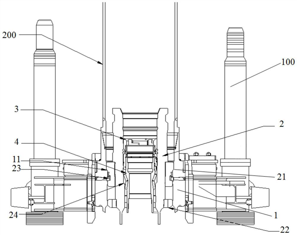
[0032] refer to figure 1 , the subsea wellhead assembly for shallow water includes a low pressure wellhead 1 , a high pressure wellhead 2 , an annular seal assembly 3 and a casing hanger 4 .

[0033] The low pressure wellhead 1 is located in the outermost layer, the high pressure wellhead 2 is set in the low pressure wellhead 1, the casing hanger 4 is seated in the high pressure wellhead 2; the annular seal assembly 3 is sealed between the casing hanger 4 and the high pressure wellhead 2. At the same time, the locking of the annular seal assembly 3 between the casing hanger 4 and the high pressure wellhead 2 is realized.

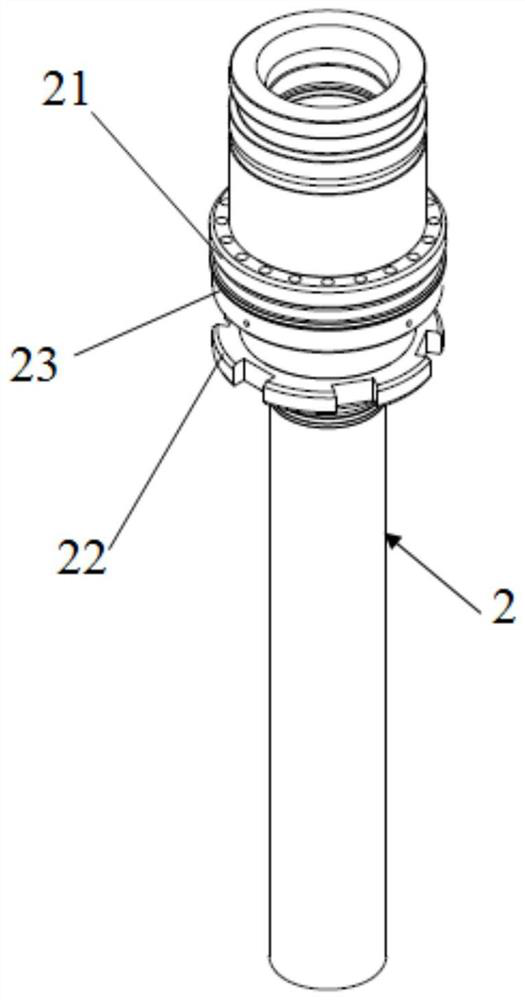
[0034] Preferably, the longitudinal centerlines of the low-pressure wellhead 1, the high-pressure wellhead 2,...

Embodiment 2

[0058] Embodiment 2: A kind of installation method of underwater wellhead assembly in shallow water sea area

[0059] Embodiment 2 provides an installation method of an underwater wellhead assembly in a shallow sea area, using the underwater wellhead assembly provided in Embodiment 1, and the method includes the following steps:

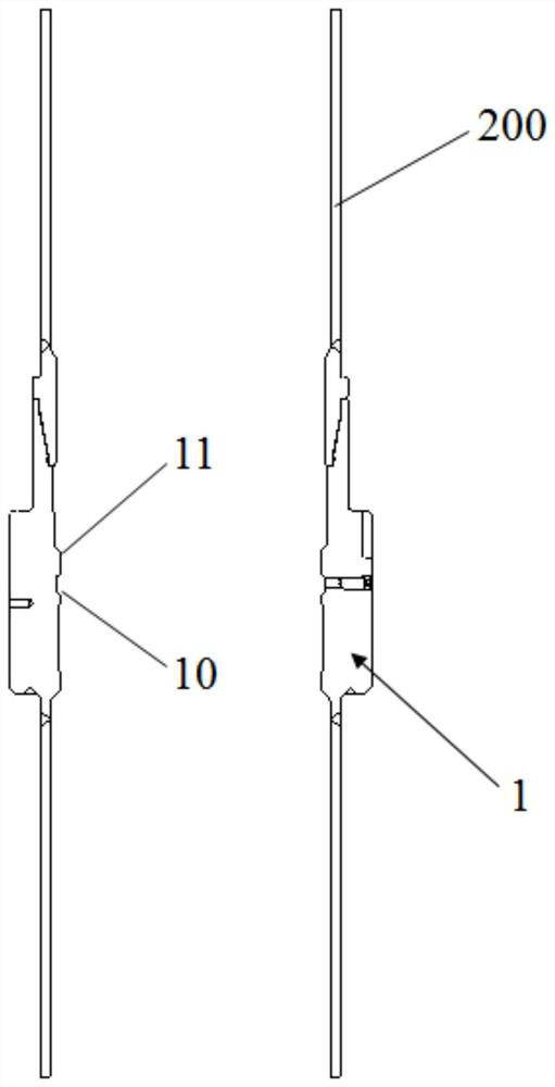
[0060] Step S1: the lower part of the low pressure wellhead 1 is connected with a plurality of surface conduits; the top of the low pressure wellhead 1 is butted with a plurality of tieback joints 200, wherein the top of the low pressure wellhead 1 and the lowest tieback joint 200 pass through the reverse connection. Tighten the butt clockwise, and connect the multiple tie-back joints 200 above the lowest tie-back joint 200 by clockwise tightening and butt joint; control the low-pressure wellhead 1 and the surface conduit to go down into the wellhead together through the tie-back nipple 200 until the installed in the intended location.

[0061] Step...


PUM


Abstract

The invention discloses an underwater wellhead assembly for shallow water, which comprises a low-pressure wellhead, a high-pressure wellhead, a casing hanger and an annular sealing assembly, and is characterized in that the high-pressure wellhead is arranged in the low-pressure wellhead; the casing hanger is arranged in a high-pressure wellhead; the annular sealing assembly is arranged between the casing hanger and the high-pressure well mouth in a sealed mode, and locking of the annular sealing assembly between the casing hanger and the high-pressure well mouth is achieved. The invention discloses an underwater wellhead assembly for shallow water, which is locked between a casing hanger and a high-pressure wellhead through an annular sealing assembly, is very good in sealing performance and locking effect, is simple in tie-back operation, improves the installation reliability and operation efficiency of an underwater Christmas tree, and reduces the installation difficulty and uncertainty.

Description

technical field [0001] The invention relates to the technical field of oil drilling and production equipment, in particular to an underwater wellhead assembly for shallow water. Background technique [0002] Subsea wellheads are widely used in the development of deepwater oil and gas fields for deepwater drilling and completion operations and oil and gas production. Due to the conflict of sea use, geopolitical influence, and marginal oilfield problems, drilling and oil and gas production in shallow waters can be used as oilfields in restricted areas. A mode of development. [0003] The existing shallow water underwater wellhead device is generally a mudline hanger device. The mudline hanger is set below the mud surface. Generally, 3-4 layers of casing are connected back to the drilling platform layer by layer to establish a wellbore. The back connection process is complex and efficient. Low and time consuming. Among them, the water depth is generally 300 meters, shallow wa...

Claims


Application Information

Patent Timeline
Patent Type & Authority Applications(China)
IPC IPC(8): E21B33/035E21B33/038E21B33/043E21B33/047
CPCE21B33/035E21B33/043E21B33/047E21B33/038
Inventor 米立军李中刘书杰刘化国范白涛王名春隋中斐张会增王彬于小涛
Owner CHINA NATIONAL OFFSHORE OIL (CHINA) CO LTD
Why Eureka
Eureka Blog
Learn More