
Method for field fixed point zero-dead-zone autonomous soft landing of subminiature unmanned rotor aircraft

A rotorcraft, ultra-small technology, applied in the direction of aircraft lander, etc., can solve the problems of target size, frequent changes in shape, errors, large frame errors before and after images, etc.

Active Publication Date: 2014-02-19
SHANGHAI UNIV
View PDF8 Cites 28 Cited by
  • Summary
  • Abstract
  • Description
  • Claims
  • Application Information

AI Technical Summary

Problems solved by technology

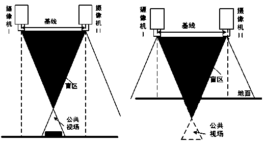
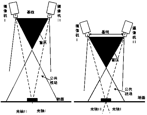
In this case, the UAV, the airborne camera and the landing target all have large or sudden relative motions, and the autonomous landing system will encounter the following problems: ①The large deviation not only blurs or jumps the continuous video image, but also makes the image The error between the front and rear frames becomes larger, and even the target area is out of the public field of view; ②The rotorcraft, the camera and the landing target undergo high-frequency irregular relative motion, resulting in frequent changes in the size and shape of the captured target, which increases the difficulty of dynamic image matching; ③The self-vibration of the rotorcraft and the high-frequency and large-scale attitude changes lead to poor quality of the collected images and videos, which increases the difficulty of image processing, coupled with the limited processing capacity of the airborne equipment, resulting in a time lag in the altitude information feedback; ④Aircraft The attitude change of the airborne camera affects the attitude of the airborne camera in real time. If the two do not coordinate and control, the sudden change of the attitude of the rotorcraft will cause a large error

Method used


Image

  • Method for field fixed point zero-dead-zone autonomous soft landing of subminiature unmanned rotor aircraft
  • Method for field fixed point zero-dead-zone autonomous soft landing of subminiature unmanned rotor aircraft
  • Method for field fixed point zero-dead-zone autonomous soft landing of subminiature unmanned rotor aircraft

Examples


Embodiment Construction

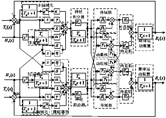
[0050] A preferred example of the present invention is described in detail as follows: see Figure 1~Figure 7 , this ultra-small unmanned rotorcraft fixed-point zero-blind zone autonomous soft landing method is characterized in that the vestibulo-oculomotor reflex of the binocular eyeballs and the anisotropic movement are fused together, which is the compound movement of the two, and based on this human-like The mathematical model of the eye's compound motion control system controls the binocular camera's onboard pan-tilt, so that the unmanned rotorcraft can still keep the landing target in the common field of view of the two cameras in harsh environments.

[0051] join Figure 6 , this bionic control method based on the compound motion of bionic heterotropic motion and vestibular-ocular reflex fusion is used for the field fixed-point landing system of ultra-small UAVs. The system includes ground control system 1 and airborne control unit and small unmanned aerial vehic...


PUM


Abstract

The invention relates to a method for field fixed point zero-dead-zone autonomous soft landing of a subminiature unmanned rotor aircraft. According to the method, a landing system is started and switched, a landing area is searched, an attitude sensor measures attitude positions of a small unmanned aircraft, and a visual sensor collects target information of a camera; the attitude position information and the target information undergo operation processing according to a set input relationship of eyeball compound motion after being subjected to corresponding A / D conversion and digital filtering, then, the relative deviation between a tracking object and the optical axis of the camera can be obtained, and corresponding scale conversion is carried out; the processed information serves as a control law of an airborne platform controller and respectively controls airborne platform motors, and therefore properties of the eyeball compound motion can be achieved. By means of the method, an airborne platform can be adjusted in real time and autonomous tracking on suspicious motion targets by the unmanned aircraft at a jolting environment can be achieved according to the position information of the tracked motion targets and the attitude information of the unmanned aircraft, and a certain stabilizing effect on tracking images can be achieved.

Description

technical field [0001] The invention relates to an autonomous soft landing method for an ultra-small rotorcraft in the field with a fixed point and zero blind zone. The feature of the method is that it compensates for the attitude change of the ultra-small unmanned rotorcraft and the blind area of ​​the traditional binocular vision system when the ultra-small unmanned rotorcraft lands autonomously in a turbulent environment based on the compound motion control mechanism of binocular anisotropy and vestibular eye movement reflex. Background technique [0002] The characteristic size of the ultra-small unmanned rotorcraft is between 120-180cm. It has the characteristics of vertical take-off and landing, hovering in the air, good maneuverability, easy portability, good concealment, and low cost. It is widely used in modern military, anti-terrorism, and public safety. And civil and other aspects have very broad application prospects. [0003] It is precisely because of the abov...

Claims


Application Information

Patent Timeline
Patent Type & Authority Applications(China)
IPC IPC(8): B64D45/08
Inventor 李恒宇黄潮炯刘恒利谢少荣罗均
Owner SHANGHAI UNIV
Learn More