
Method, UE and access network device capable of fusing network data transmission

A data transmission method and technology for accessing network equipment, applied in digital transmission systems, network topology, hybrid transportation, etc., can solve problems such as affecting user experience, terminal power consumption, and network operators losing control of terminals, achieving savings The effect of operating expenses, fast data flow switching, and avoiding data loss

Active Publication Date: 2014-02-12
ZTE CORP
View PDF1 Cites 16 Cited by
  • Summary
  • Abstract
  • Description
  • Claims
  • Application Information

AI Technical Summary

Problems solved by technology

Although 3GPP has formulated the relevant protocols for interworking between 3GPP networks and WLAN networks, there are still some deficiencies in the current Interworking architecture. Data flow switching is relatively slow when moving between networks, and a large amount of data will be lost during the data flow switching process of the two networks, which will affect user experience
Another important point is that the current architecture still relies on operators having independent 3GPP networks and independent and complete WLAN networks, which requires operators to operate and maintain multiple networks at the same time. CAPEX) larger
In addition, the selection of the WLAN network under this architecture is completely determined by the terminal, and the network operator loses control over the terminal, and cannot implement the overall resource allocation according to the prior network planning.
Furthermore, under the Interworking architecture, in order to realize the joint transmission of 3GPP and WLAN, the terminal needs to turn on two sets of transceivers at the same time, which also has a great impact on the power consumption of the terminal

Method used


Image

  • Method, UE and access network device capable of fusing network data transmission
  • Method, UE and access network device capable of fusing network data transmission
  • Method, UE and access network device capable of fusing network data transmission

Examples


Embodiment 1

[0056] This embodiment provides as figure 1 The system shown includes: 3GPP core network, 3GPP access network, user equipment (UE): where the user equipment accesses the 3GPP access network through the WiFi module (or WLAN module or WLAN entity), and establishes with the 3GPP access network Wireless connection based on WiFi transmission, and access to the 3GPP core network through the 3GPP access network. That is to say, both the UE and the 3GPP access network in this paper support WLAN access, and can support data transmission and reception using the WiFi module.

[0057] The UE and the 3GPP access network equipment for realizing converged network data transmission are introduced respectively below.

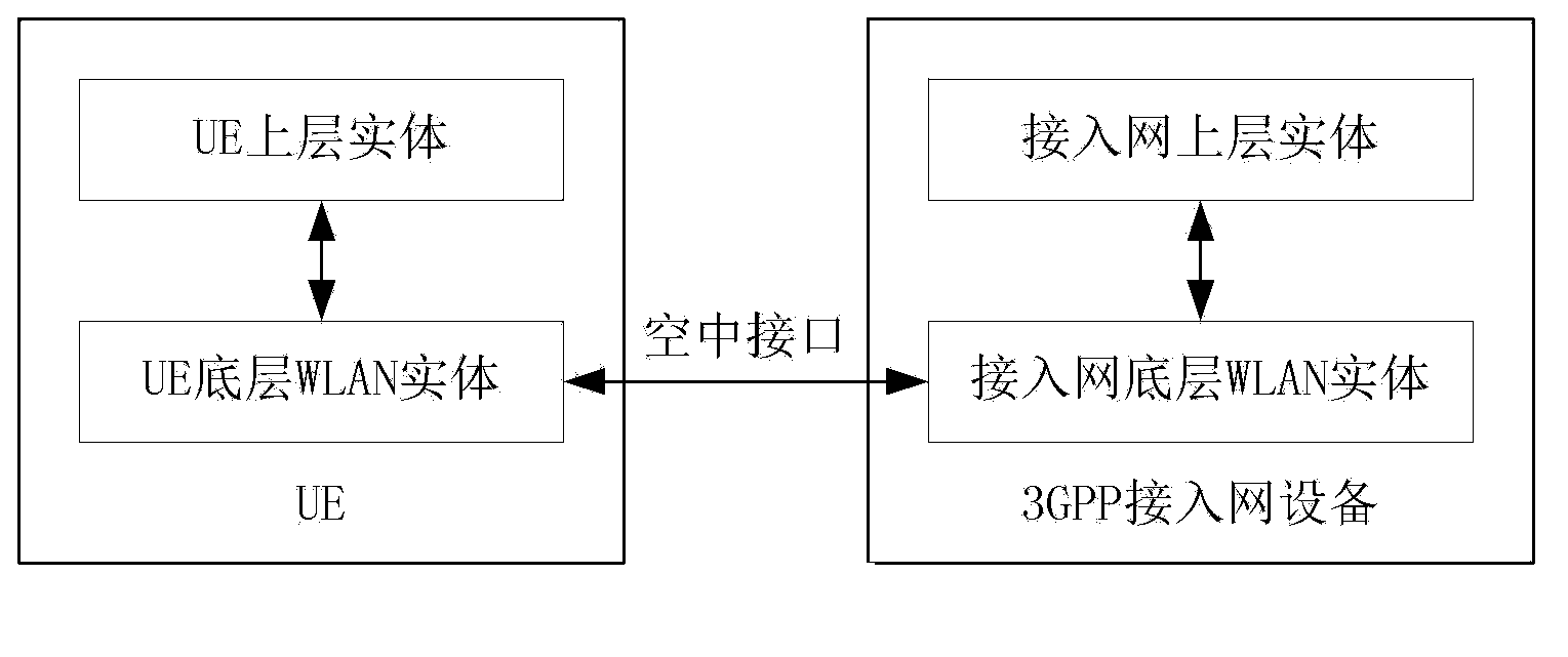
[0058] Such as figure 2 As shown, the UE in this embodiment includes a UE bottom layer WLAN entity and a UE upper layer entity, where:

[0059] The WLAN entity at the bottom layer of the UE is used to encapsulate the signaling and / or data sent by the upper layer entity of th...

Embodiment 2

[0079] This embodiment introduces the processing performed by the user equipment and the processing performed by the access network device in the data transmission method for implementing a converged network.

[0080] User equipment performs processing such as Figure 7 shown, including the following steps:

[0081] Step 10, the WLAN entity at the bottom layer of the UE encapsulates the signaling and / or data delivered by the upper layer entity of the UE into a WLAN protocol format and sends it to the 3GPP access network through the air interface;

[0082] In step 11, the underlying WLAN entity of the UE receives the signaling and / or data sent by the 3GPP access network through the air interface, decapsulates it and sends it to the upper entity of the UE.

[0083] The above method further includes: the UE upper layer entity establishes a control plane connection and / or a user plane connection with the 3GPP access network through the UE bottom layer WLAN entity and the air interf...

application example 1

[0096] Such as Figure 9 As shown, this example takes the integration of LTE and WLAN as an example, and the network element of the access network is an eNB supporting WLAN access, and the description is as follows.

[0097] The UE that supports WLAN access accesses the access network eNB that supports WLAN access by means of the underlying WLAN air interface transmission mechanism, and finally establishes with the core network element MME and S / P-GW (S-GW and P-GW) respectively. Control plane and user plane connection.

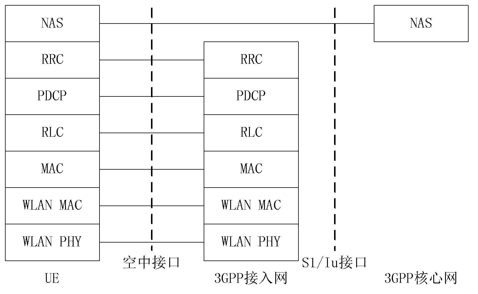
[0098] The control plane interface protocol stack between the UE and the network side is as follows: Figure 10 Shown:

[0099] Between the UE and the eNB, above the lower WLAN PHY and WLAN MAC layer entities, it is handled by the LTE RRC layer entity and the LTE PDCP layer entity. After the RRC signaling between the UE and the eNB is processed by the LTE PDCP layer entity (this processing may include header compression, encryption, etc.), it is transmitte...


PUM


Abstract

The invention discloses a method, UE and network device capable of fusing network data transmission to achieve network fusion of 3GPP and WLAN. The UE is used for executing the following steps that a UE bottom layer WLAN entity encapsulates the signaling and / or the data issued by a UE upper layer entity to be a WLAN protocol format and sends the encapsulated signaling and / or data to the 3GPP access network through an air interface, and the UE bottom layer WLAN entity receives the signaling and / or the data sent by the 3GPP access network through the air interface, unpacks the signaling and / or the data and sends the unpacked signaling and / or data to the UE upper layer entity. The access network device is used for executing the following steps that an access network bottom layer WLAN entity encapsulates the signaling and / or the data issued by an access network upper layer entity to be a WLAN protocol format and sends the encapsulated signaling and / or data to the UE through the air interface, and the access network bottom layer WLAN entity receives the signaling and / or the data sent by the UE through the air interface, unpacks the signaling and / or the data and sends the unpacked signaling and / or data to the access network upper layer entity. By means of the method, UE and network device, the further fusion between the 3GPP and the WLAN is finished.

Description

technical field [0001] The invention relates to a mobile communication system, in particular to a data transmission method, UE, and access network equipment for realizing a converged network. Background technique [0002] With the continuous evolution of wireless communication technologies and standards, mobile packet services have been greatly developed, and the data throughput capability of a single terminal is constantly improving. Taking the Long Term Evolution (LTE for short) system as an example, it can support data transmission at a maximum downlink rate of 100 Mbps within a 20M bandwidth. In the subsequent enhanced LTE (LTE Advanced) system, the data transmission rate will be further improved, even Can reach 1Gbps. [0003] The expansive growth of terminal data traffic has made the existing network resources gradually overwhelmed, especially when the new generation of communication technologies (such as 3G and LTE) cannot be widely deployed on the network, followed ...

Claims


Application Information

Patent Timeline
Patent Type & Authority Applications(China)
IPC IPC(8): H04W28/06H04W76/02
CPCH04L12/4633H04L12/28H04W76/00H04L12/6418H04W80/00H04W76/12H04L69/08H04W72/1215H04W84/042H04W84/12H04W92/10
Inventor 和峰
Owner ZTE CORP
Learn More