
Hybrid optical amplifier with optimized noise figure

A hybrid amplifier and noise figure technology, applied in semiconductor amplifier structures, lasers, phonon exciters, etc., can solve problems that do not consider NF optimization

Inactive Publication Date: 2014-02-12
FINISAR
View PDF3 Cites 6 Cited by
  • Summary
  • Abstract
  • Description
  • Claims
  • Application Information

AI Technical Summary

Problems solved by technology

However, if the overall gain of the HA NF is assumed to be fixed, then, in the case of variable gain HA, the optimization of the NF is not considered at all

Method used


Image

  • Hybrid optical amplifier with optimized noise figure
  • Hybrid optical amplifier with optimized noise figure
  • Hybrid optical amplifier with optimized noise figure

Examples


Embodiment Construction

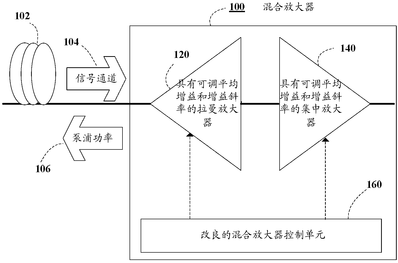
[0028] figure 1 A schematic diagram of a variable gain hybrid amplifier 100 according to an embodiment disclosed herein is shown. The hybrid amplifier 100 is connected to the fiber segment 102 and is designed to amplify the WDM signal channel 104 . The hybrid amplifier 100 includes two amplifier sections: a variable-gain Raman amplifier (RA) 120 and a variable-gain focusing amplifier (LA) 140 . Each amplifier features adjustable average gain and gain slope functions. Raman amplifier 120 injects pump power 106 into fiber segment 102 in a backward pump configuration, thereby amplifying WDM signal path 104 as it propagates through the fiber segment. WDM signal path 104 then enters HA100 and is further amplified by LA140. The hybrid amplifier 100 is controlled by a "modified" control unit 160 .

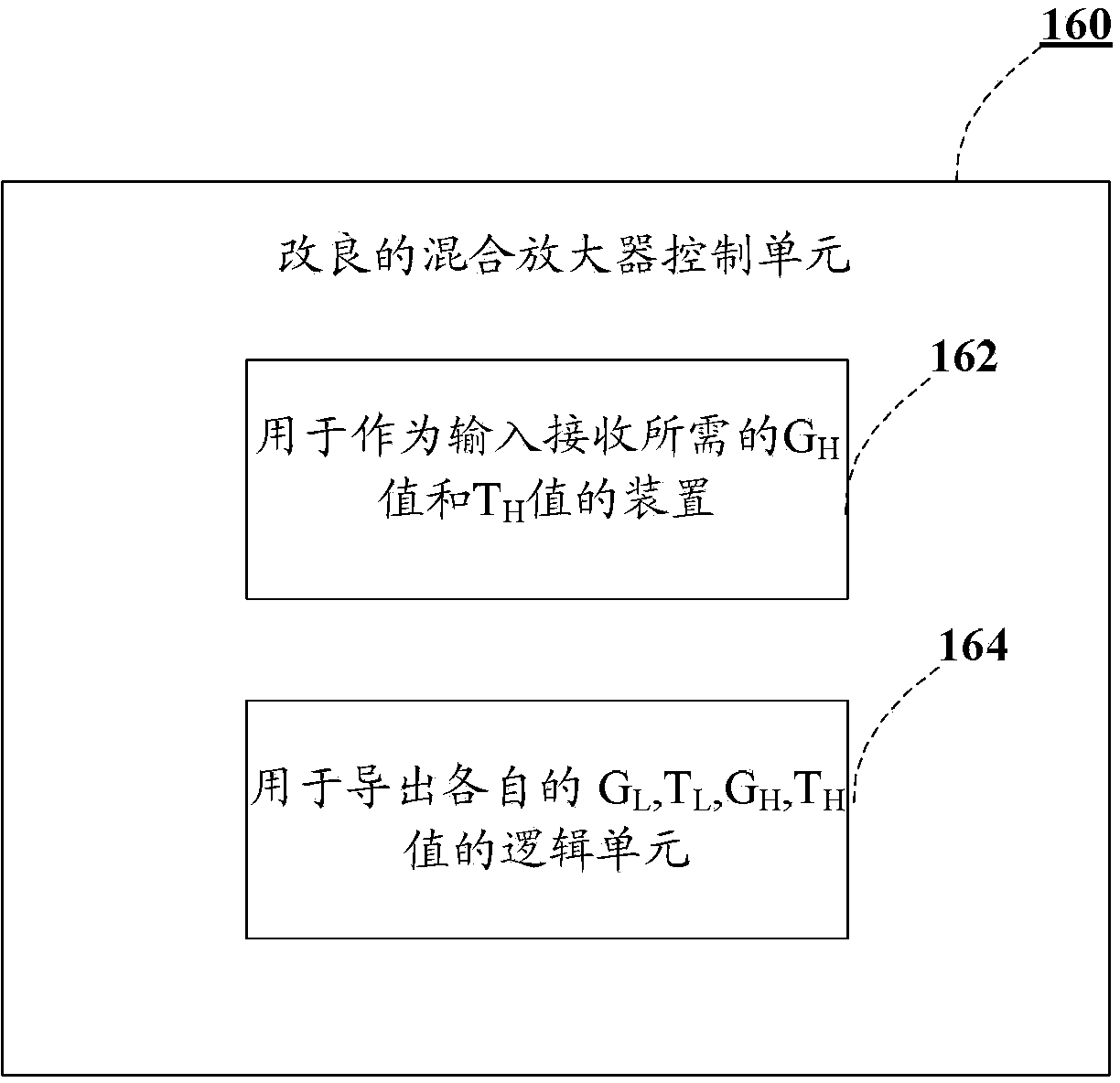
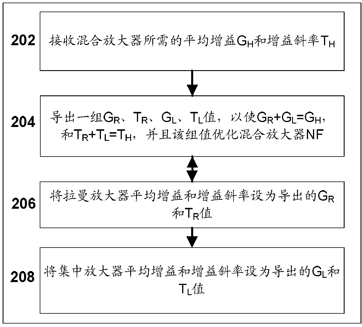
[0029] Details of an embodiment of the modified control unit 160 are in Figure 1a is schematically shown in the diagram, and its operation consists of figure 2 The flowchart illus...


PUM


Abstract

Methods for optimizing a noise figure of a variable gain hybrid amplifier (HA) which includes a variable gain Raman amplifier with adjustable average gain G R and gain tilt T R and a variable gain lumped amplifier with adjustable average gain G L and gain tilt T L . In various embodiments, the methods include receiving as input a required hybrid amplifier average gain G H value and a required gain tilt T H value and deriving a set of G R , T R , G L and T L values which yield an optimal optimized hybrid amplifier NF and satisfy the conditions G R + G L = G H and that T R + T L is within a specified hybrid amplifier operating tilt range. In some embodiments, the derived T R and T L values satisfy the condition T R + T L = T H . A hybrid amplifier implementing a method disclosed herein includes a modified control unit configured to control both average gain and gain tilt parameters of the Raman amplifier and the lumped amplifier to satisfy the conditions above.

Description

technical field [0001] Embodiments disclosed herein relate generally to fiber amplifiers for fiber optic communication systems, and more particularly, to hybrid concentrated Raman amplifiers. Background technique [0002] Modern optical communication systems utilize optical amplifiers to amplify a wavelength division multiplexed (WDM) signal channel as it travels through the system (modern optical communication system). These amplifiers can be placed at the receiving end and the transmitting end of the system, and can also be placed between the various transmission fiber segments that comprise the system. [0003] Compared with other amplifiers, optical amplifiers are characterized by their gain and noise figure (NF), which quantifies the noise introduced into the system by the amplifier. For WDM systems, when the WDM signal channel occupies a signal wavelength band, the optical amplifier is also characterized by the spectral dependence of gain and NF in the wavelength band...

Claims


Application Information

Patent Timeline
Patent Type & Authority Applications(China)
IPC IPC(8): H04B10/291
CPCH01S2301/02H04B10/2914H01S5/50H01S3/2375H01S3/30H01S3/06758H04B10/2916H01S3/1608H01S2301/04H01S3/302
Inventor 汤莫尔·埃利亚胡埃亚尔·萨里德尤瑞·盖拉大卫·梅纳什
Owner FINISAR
Learn More