
Tray and electronic card connector

A technology for electronic cards and connectors, which is applied in the direction of connection, parts of connecting devices, and devices for preventing wrong connection, etc., can solve problems such as being unsuitable for carrying electronic cards on trays

Inactive Publication Date: 2014-02-12
MOLEX INC
View PDF8 Cites 5 Cited by
  • Summary
  • Abstract
  • Description
  • Claims
  • Application Information

AI Technical Summary

Problems solved by technology

In order to prevent the user from inserting the electronic card in the wrong direction, causing the electronic card to fail to form a correct electrical connection with the electronic card connector, the general electronic card connector is designed with an anti-mis-insertion structure based on the shape of the electronic card, such as the Taiwan New Patent Announcement No. 532533 (corresponding to Chinese patent CN01228673.7, corresponding to US patent US6478630) discloses an electronic card connector with an anti-mis-insertion structure
[0003] However, the error-proof structure of this kind of electrical connector is not suitable for the combination of using the tray to carry the electronic card.

Method used


Image

  • Tray and electronic card connector
  • Tray and electronic card connector
  • Tray and electronic card connector

Examples


Embodiment Construction

[0056] The aforementioned and other technical content, features and effects of the present invention will be clearly presented in the following detailed description of a preferred embodiment with reference to the accompanying drawings.

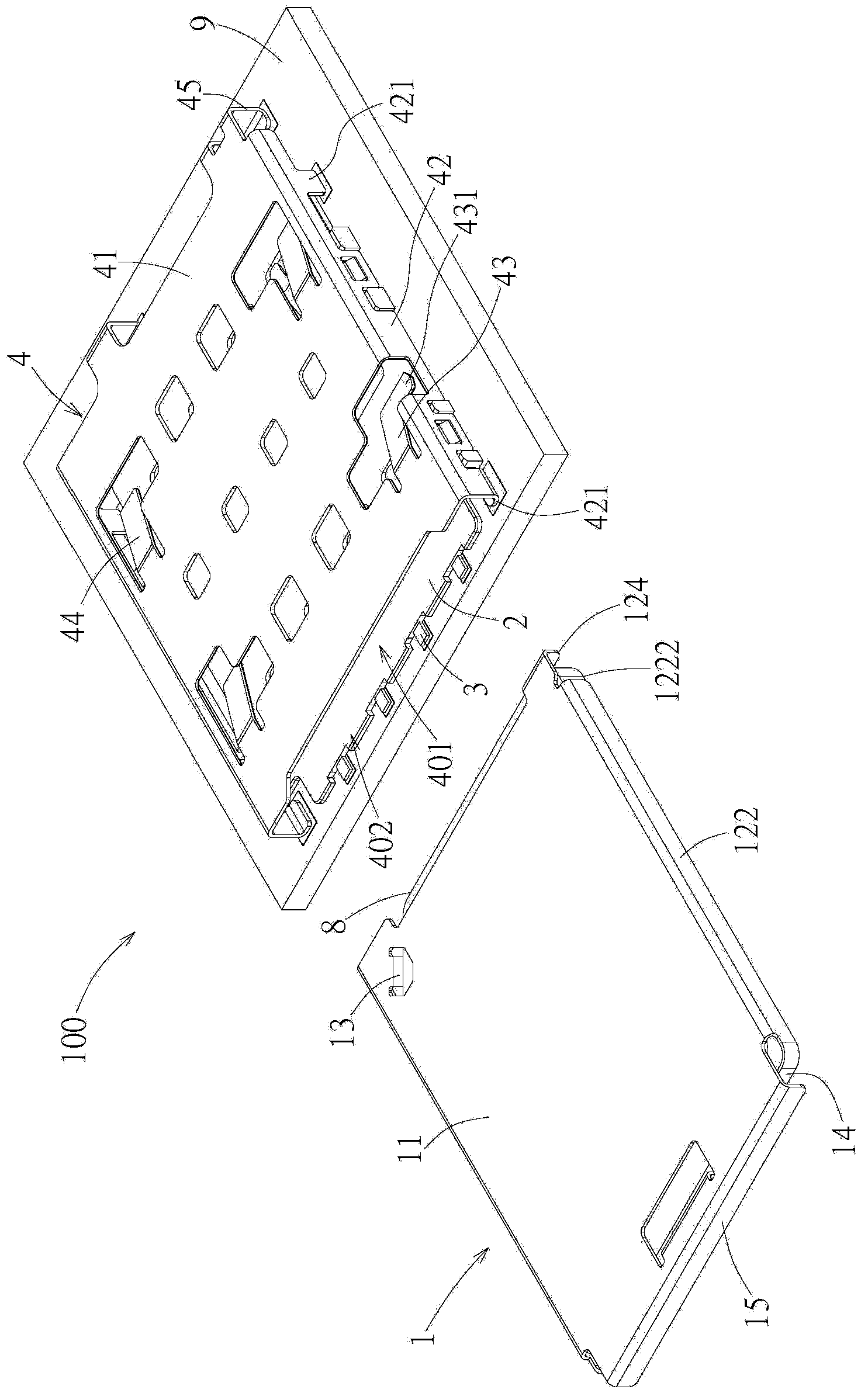
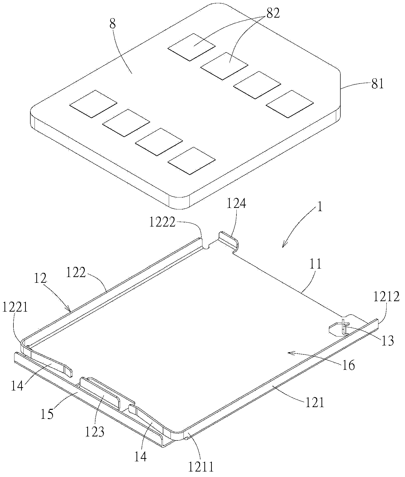
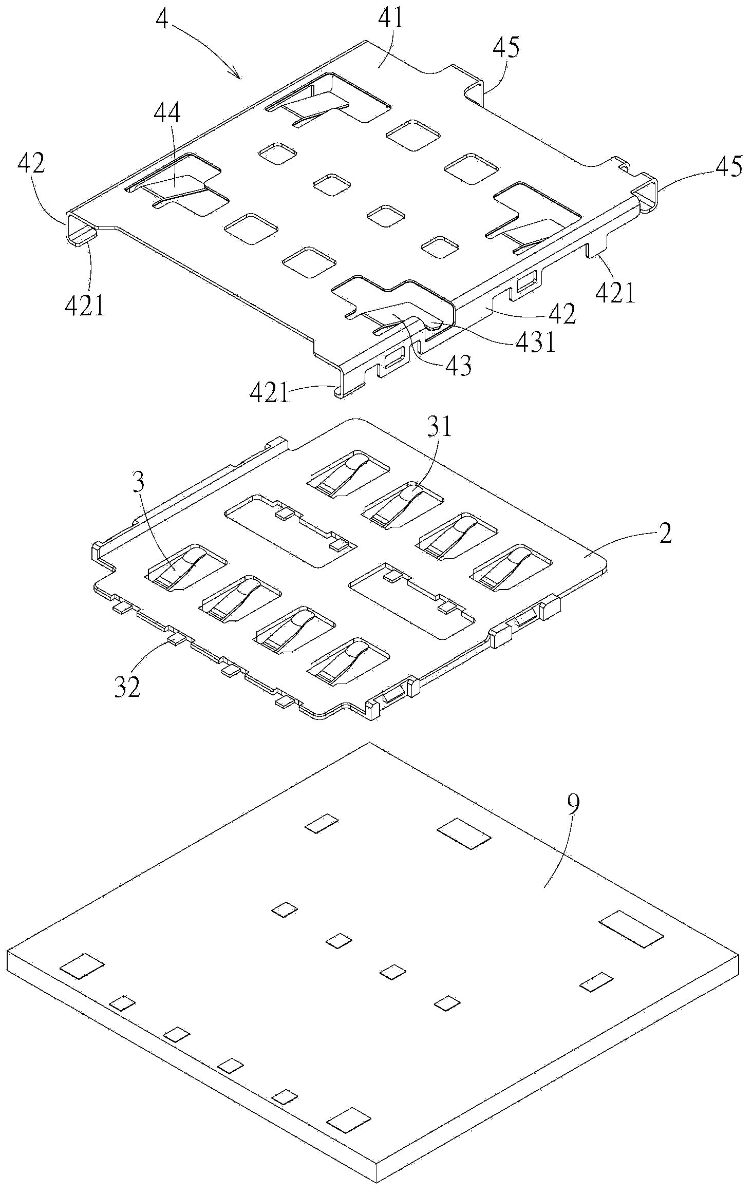
[0057] refer to Figure 1 to Figure 3 , a preferred embodiment of the electronic card connector 100 of the present invention is suitable for being disposed on a circuit board 9 to electrically connect an electronic card 8 . In this embodiment, the electronic card 8 is a Subscriber Identity Module (SIM) card, and has a cut corner 81 for positioning. The electronic card connector 100 includes a tray 1 , an insulating body 2 , a plurality of terminals 3 and a metal cover 4 .

[0058] refer to figure 2 , Figure 4 and Figure 5, the tray 1 is integrally formed by a metal plate for accommodating the electronic card 8 . The tray 1 includes: a rectangular base plate 11 , a blocking wall unit 12 , a positioning wall 13 , two retaining elastic pi...


PUM


Abstract

The invention provides a tray and an electronic card connector. The electronic card connector comprises the tray, an insulation body, multiple terminals which are arranged on the insulation body, and a metal cover. The tray comprises a substrate which presents to be a rectangular shape, a blocking wall unit, a positioning wall and at least one holding elastic sheet. The holding elastic sheet is formed in a way that the blocking wall unit extends so that the electronic card is abutted and held. The metal cover is covered on the insulation body, and an inserting space which is used for inserting the tray, and an inlet are commonly defined. The metal cover comprises a cover plate part which is opposite to the insulation body in a spacing way and a reverse insertion resistant elastic sheet which is formed on the cover plate part. The reverse insertion resistant elastic sheet is formed in the way that the cover plate part extends into the inserting space and extends in an oblique way away from the inlet, and the reverse insertion resistant elastic sheet is provided with a stop blocking part which is formed on the tail end and laterally extends in a protruding way. With application of the reverse insertion resistant elastic sheet, the tray is ensured to be inserted into the inserting space in correct direction.

Description

technical field [0001] The invention relates to a tray and an electronic card connector containing the tray, in particular to a tray capable of holding an electronic card and an electronic card connector capable of preventing the tray from being reversely inserted. Background technique [0002] The electronic card connector is used for inserting an electronic card, and serves as a medium for electrically connecting the electronic card to the circuit board. In order to prevent the user from inserting the electronic card in the wrong direction, causing the electronic card to fail to form a correct electrical connection with the electronic card connector, the general electronic card connector is designed with an anti-mis-insertion structure based on the shape of the electronic card, such as the Taiwan New Patent Publication No. 532533 (corresponding to Chinese Patent CN01228673.7, corresponding to US Patent No. 6478630) discloses an electronic card connector with an anti-misplu...

Claims


Application Information

Patent Timeline
IPC IPC(8): G06K13/08H01R13/639H01R13/64
Inventor 洪丽琴林健兴
Owner MOLEX INC
Learn More