
Method for producing a striplight and striplight

A light strip and carrier technology applied to flexible LED strips. ,In the field of manufacturing light strips, it can solve the problems of high cost manufacturing of lighting devices, and achieve the effect of simple method and simple electrical contact

Active Publication Date: 2014-02-12
OPTOTRONIC GMBH
View PDF7 Cites 1 Cited by
  • Summary
  • Abstract
  • Description
  • Claims
  • Application Information

AI Technical Summary

Problems solved by technology

Such lighting fixtures can only be manufactured cost-intensively

Method used


Image

  • Method for producing a striplight and striplight
  • Method for producing a striplight and striplight
  • Method for producing a striplight and striplight

Examples


Embodiment Construction

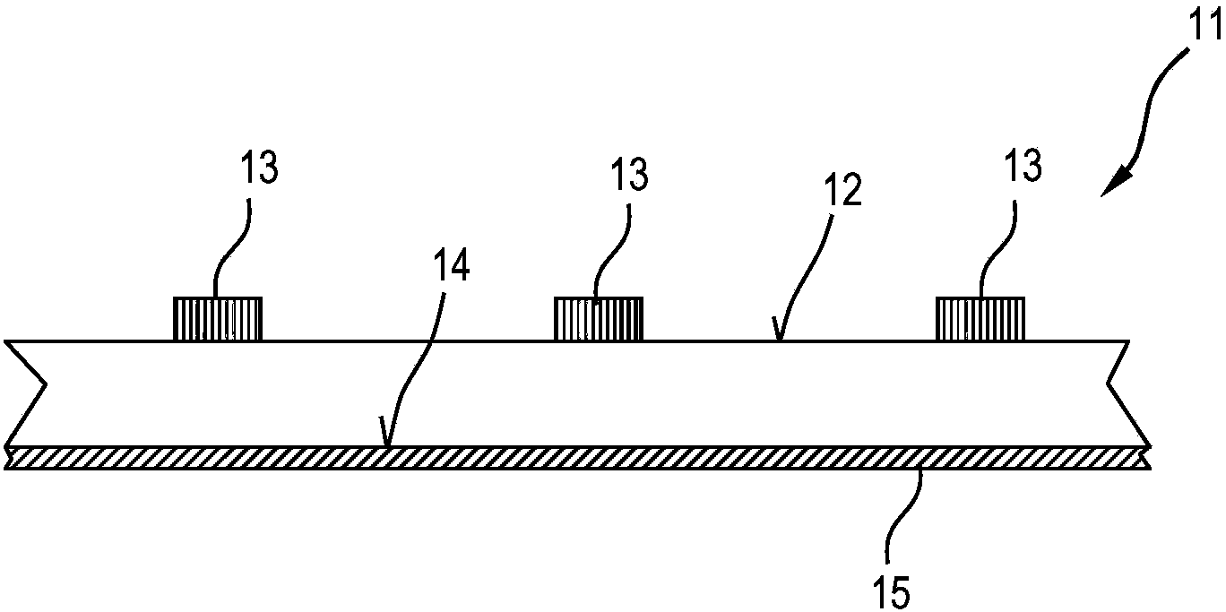
[0037] figure 1 A partial view of a strip-shaped carrier 11 is shown in side view, which is equipped with semiconductor light sources in the form of light-emitting diodes 13 on its front side 12 . The carrier 11 can, for example, be flexible and consist of polyimide. The front side 12 can also have a strip conductor structure (not shown). also like figure 2 As shown, two parallel electrical conductors 15 in the form of copper wires with a circular cross-section lie loosely on the back side 14 of the carrier 11 and are also in contact with the back side 14 .

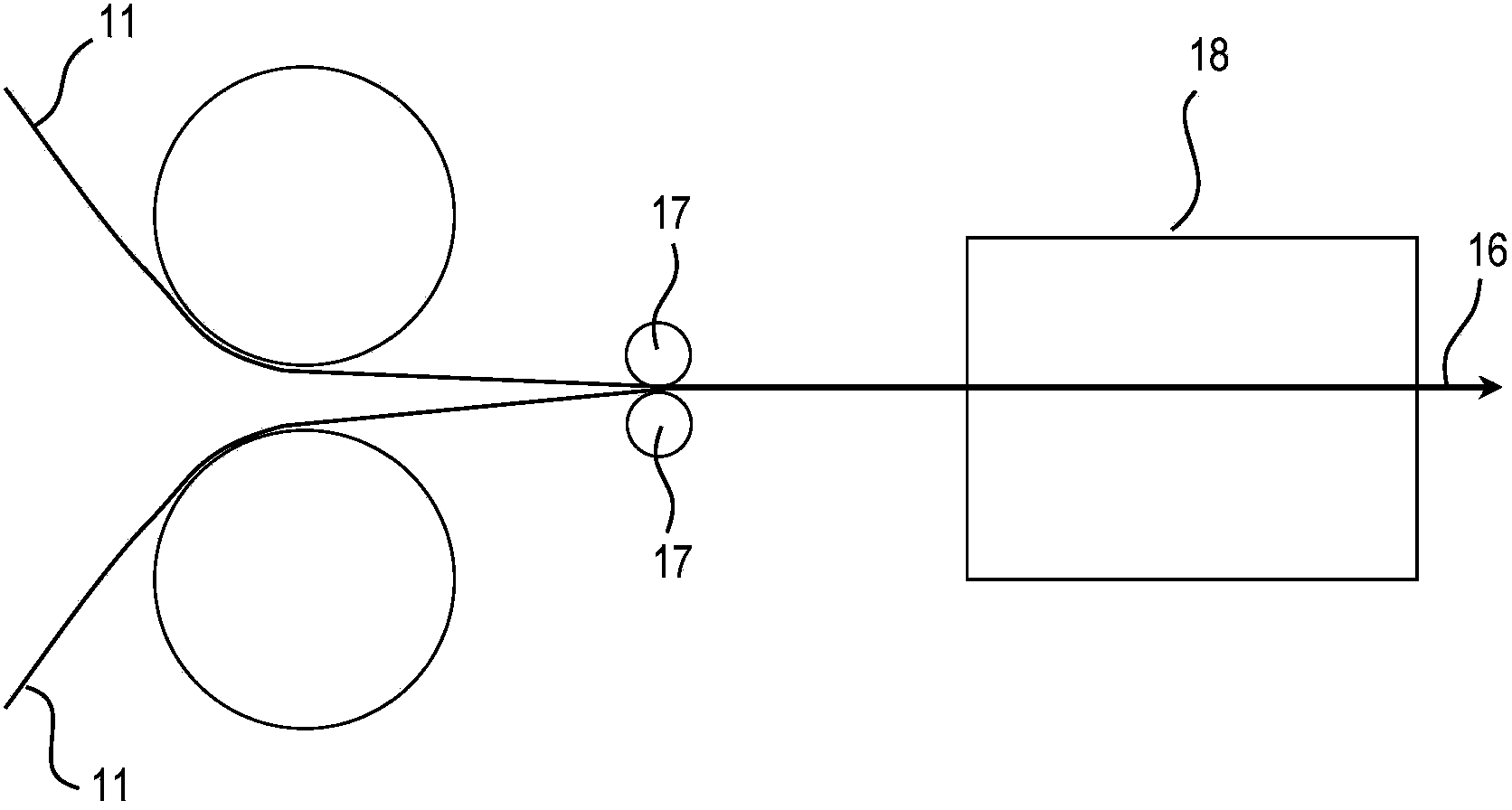
[0038] image 3 The structure used to manufacture the light bar 16 is shown. In this construction, initially an assembled strip-shaped carrier 11 and two electrical lines 15 are provided. For example, electrical wire 15 is loosely mounted on the back side 14 of carrier 11 by wire roller 17, as figure 1 or figure 2 as shown.

[0039] The elements 11 to 15 are also conveyed further into an embedding machine 18, fo...


PUM


Abstract

A method for producing a striplight is disclosed. Said method utilizing at least the following steps: (a) providing a strip-shaped carrier, which is populated on at least one side with a plurality of semiconductor light sources; (b) arranging at least one electrical line on the carrier; and (c) casting the at least one electrical line on the carrier. A striplight which has: a strip-shaped carrier, populated on at least one side with a plurality of semiconductor light sources; at least one electrical line, which is arranged on the carrier; and joint casting of the carrier and the at least one electrical line, is likewise disclosed.

Description

technical field [0001] The invention relates to a method for producing a light bar, wherein the method comprises providing at least one strip-shaped carrier which is equipped with a plurality of semiconductor light sources at least on one side. The invention also relates to a light bar, wherein the light bar has a strip-shaped carrier, which is equipped on at least one side with a plurality of semiconductor light sources, and an electrical line. The invention is particularly applicable to flexible LED strips. Background technique [0002] There are known light strips in which the light-emitting diodes are arranged in series on the front side of a flexible strip circuit board, for example the light strip of the type LINEARlight FLEX from the company Osram. The circuit boards can be electrically connected on the front side, for example by means of connectors or the like. Circuit boards have ribbon conductors formed with thin copper layers (not exceeding 70 microns in height)...

Claims


Application Information

Patent Timeline
Patent Type & Authority Applications(China)
IPC IPC(8): F21S4/00F21V19/00F21V23/00F21Y101/02
CPCH01L33/62H01L2924/0002F21S4/24F21Y2103/10F21Y2115/10H01L2924/00
Inventor 托马斯·普罗伊施勒
Owner OPTOTRONIC GMBH
Learn More