Brake shoe

A technology of brake brake and brake shoe, applied in the direction of brake parts, hoisting device, etc., can solve the problems of uneven braking force of brake shoe, uneven wear of friction plate, and failure of brake shoe movement. , to achieve the effect of smooth and reliable round-trip movement, uniform braking force up and down, and good movement coordination

Inactive Publication Date: 2014-02-12
包文丽
View PDF3 Cites 2 Cited by
  • Summary
  • Abstract
  • Description
  • Claims
  • Application Information

AI Technical Summary

Problems solved by technology

[0003] Although the above-mentioned brake shoe in the prior art simplifies the structure of the brake shoe and uses the fixed element or the housing of the hoist to bear the braking friction force, the structure of the brake is miniaturized and simple, but due to the The direction of the dynamic friction force does not pass through the upper and lower surfaces of the brake shoe, so that when the brake is applied, the brake friction force produces a certain torque on the brake shoe, so that the brake shoe rotates in a certain direction. The matching of the brake shoe with the opening of the fixed element or the hoist housing will not be a surface fit, but a line contact
This brings some problems to the brake shoe: 1) because the upper and lower end faces of the brake shoe are in line contact, the opening of the brake shoe and the fixing element or the hoist housing is unreasonable; 2) because The rotation of the brake shoe, and the direction of the brake friction force does not pass through the upper and lower surfaces of the brake shoe, causing the pressure at the contact point to be greater than the brake friction force, thereby increasing the friction between the brake shoe and the fixed element or the hoist housing The surface pressure at the contact point of the opening, so that when the brake shoe moves back and forth, the wear of the brake shoe is aggravated, so that the cooperation between the brake shoe and the fixing element or the opening of the hoist housing is not good. It may cause the movement of the brake shoe to fail, making the action of the brake unreliable; 3) Due to the rotation of the brake shoe, the braking force of the brake shoe is uneven, so that the wear of the upper and lower parts of the friction plate is uneven. Even, reduce the service life of the friction plate, and may further aggravate the poor movement of the brake shoe

Method used


Image

  • Brake shoe
  • Brake shoe
  • Brake shoe

Examples


Embodiment Construction

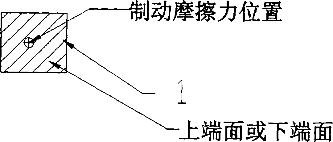
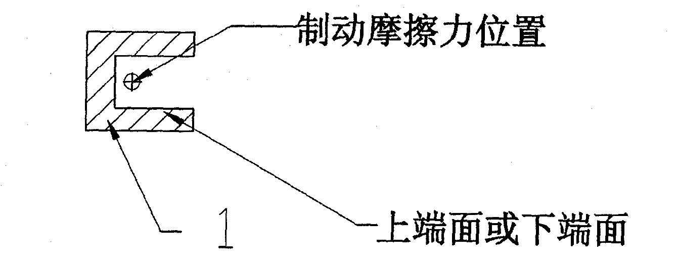
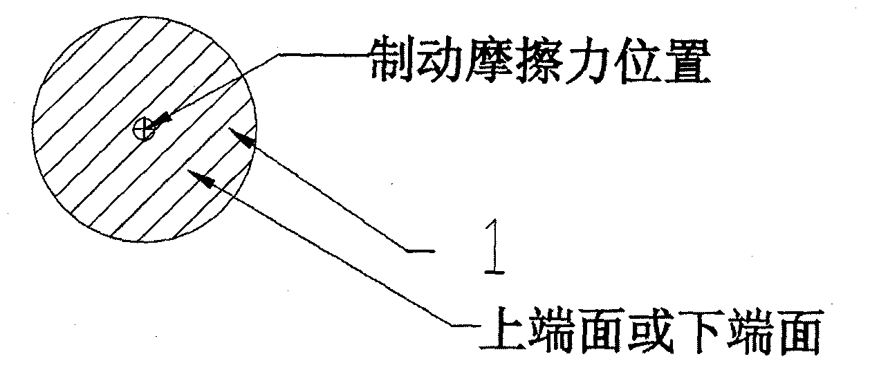
[0024] Such as figure 1 As shown, the brake shoe of the present invention includes a brake shoe 1 and a friction plate 2 . The friction plate 2 is fixedly connected to the brake shoe 1, and the connection can be fixed by bolts or other fixing methods. The friction plate 2 is fixed on the B side of the brake shoe 1 . A side braking force F of the brake shoe 1. The upper end surface and the lower end surface of the brake shoe 1 are provided with fixing elements 3 . The brake shoe 1 cooperates with the fixed element 3 through the upper end surface and the lower end surface, receives the braking friction force Ff through this cooperation, and transmits the braking friction force Ff to the fixed element 3 . The brake shoe brakes the braking surface through the friction disc 3 . It can be seen from the figure that the braking friction force Ff of the friction plate 2 passes through the upper end surface of the brake shoe 1, so that the force of the brake shoe is reasonable, so t...


PUM


Abstract

The invention discloses a brake shoe applied to a brake. The brake shoe comprises a shoe and a friction plate, wherein the friction plate is fixedly connected with the side part of the shoe; the upper end face and the lower end face of the shoe are matched with the fixed element matching surfaces of the upper end face and the lower end face of the shoe, so that braking friction force is transmitted to a fixed element; the braking friction force of the friction plate passes through the upper end face or the lower end face of the shoe. The brake shoe has the advantages of reasonable braking stress, reliable movement, long service life, simple and compact structure, convenience in installing and easiness in repairing.

Description

technical field [0001] The invention relates to a brake shoe for a traction machine brake. Background technique [0002] For the miniaturization and simple structure of the traction machine brake, the brake shoe has some new structural forms. For example, the Chinese invention patent (notification number: CN1322248C) discloses a brake shoe, the friction plate of the brake shoe is fixed on one side of the brake shoe, and the upper and lower end surfaces of the brake shoe are connected with the opening of the traction machine housing. Cooperate, the friction force of the brake shoe is supported by the hoist housing, and the direction of the brake friction force does not pass through the upper and lower end faces of the brake shoe; the side of the brake shoe opposite to the friction plate bears the braking force; the brake shoe The brake drum is braked via the inside of the brake hoist brake drum. Chinese invention patent (notification number: CN100343546C) discloses a brake ...

Claims


Application Information

Patent Timeline
Patent Type & Authority Applications(China)
IPC IPC(8): F16D65/06B66D5/08
Inventor 包文丽
Owner 包文丽
Why Eureka
Try Eureka