Steam turbine plant and control method and control system thereof

A technology of steam turbine and steam, which is applied in the direction of mechanical equipment, steam engine device, steam application, etc., and can solve problems such as pressure reduction

Inactive Publication Date: 2014-02-12
KK TOSHIBA
View PDF8 Cites 7 Cited by
  • Summary
  • Abstract
  • Description
  • Claims
  • Application Information

AI Technical Summary

Problems solved by technology

[0003] However, when the steam turbine plant is operating at part load, the pressure of the steam sent to the CO2 capture system decreases according to the reduced amount of steam in the plant

Method used


Image

  • Steam turbine plant and control method and control system thereof
  • Steam turbine plant and control method and control system thereof
  • Steam turbine plant and control method and control system thereof

Examples


no. 1 example )

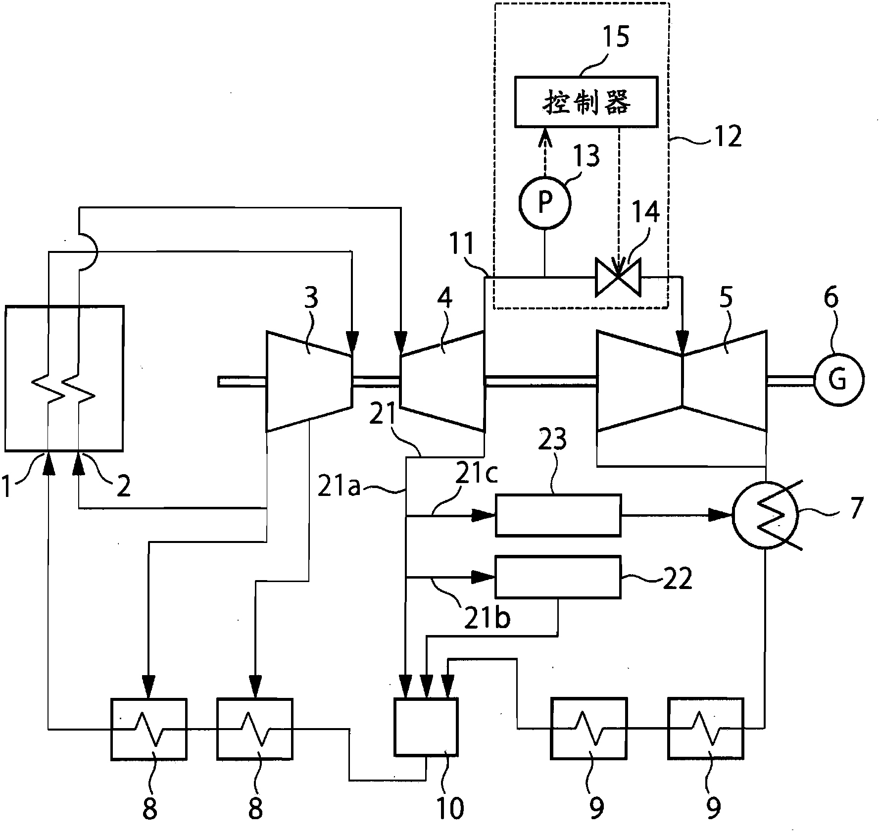
[0013] figure 1 is a schematic diagram showing the configuration of the steam turbine of the first embodiment.

[0014] figure 1 The steam turbine equipment in includes a boiler 1, a reheater 2, a high pressure turbine 3 as an example of a first turbine, an intermediate pressure turbine 4 as an example of a second turbine, a low pressure turbine 5 as an example of a third turbine, a power generation Machine 6, condenser 7, high pressure feed water heater 8, low pressure feed water heater 9 and degasser 10.

[0015] exist figure 1 In the plant in , the boiler 1 heats water to change the water into steam, and the high pressure turbine 3 is driven by the steam from the boiler 1 . The steam discharged from the high pressure turbine 3 is heated by the reheater 2 , and the intermediate pressure turbine 4 is driven by the steam from the reheater 2 . Furthermore, the low-pressure turbine 5 is driven by the steam discharged from the middle-pressure turbine 4 . The generator 6 gene...

no. 2 example )

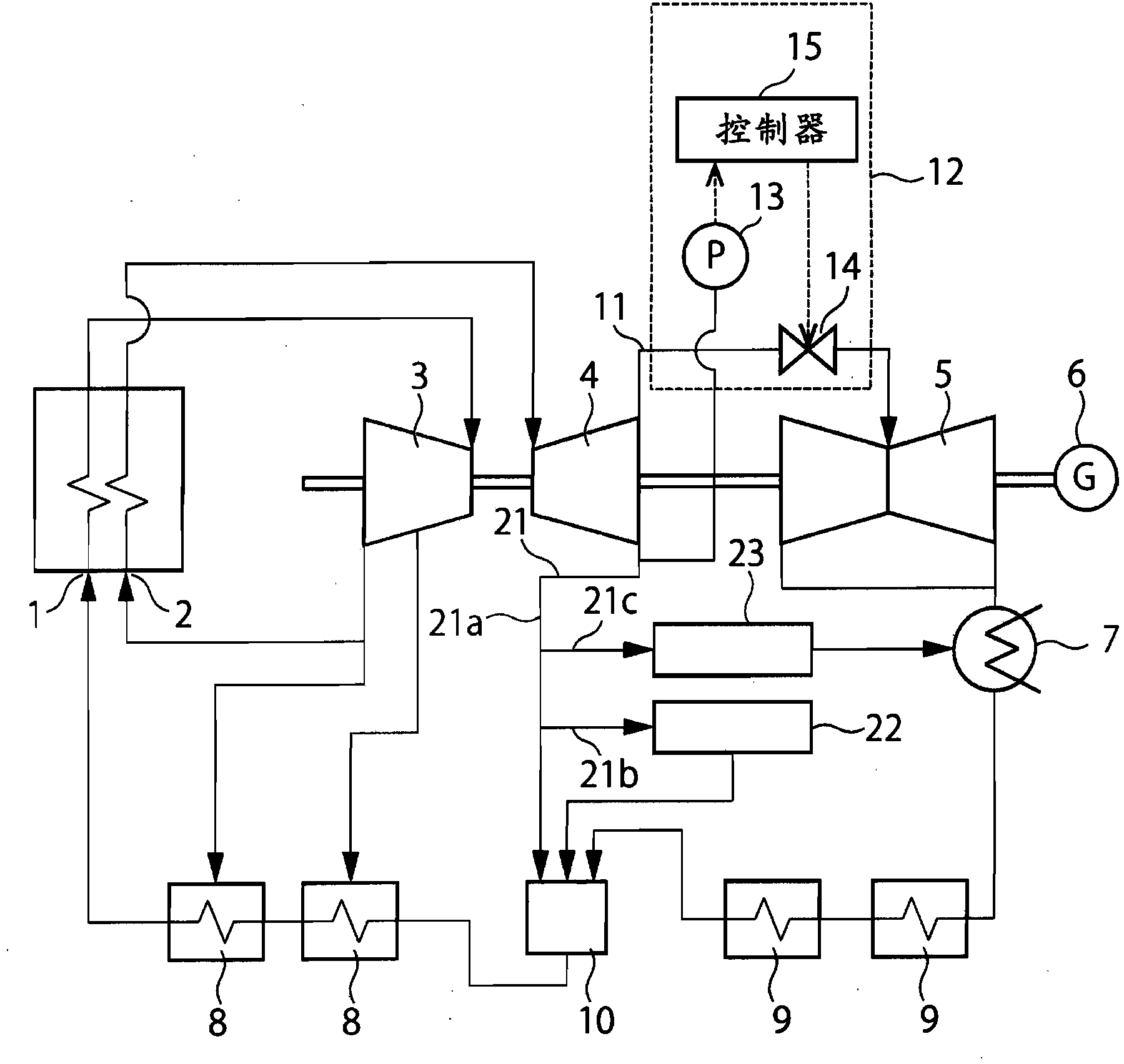
[0041] Figure 4 is a schematic diagram showing the configuration of the steam turbine of the second embodiment.


PUM


Abstract

The invention relates to a steam turbine plant and a control method and a control system thereof. In one embodiment, the steam turbine plant includes a first turbine driven by steam from a boiler, a second turbine driven by steam from a reheater, a third turbine driven by the steam exhausted from the second turbine, and a carbon dioxide capturing system including a reboiler to heat an absorbing liquid with the steam exhausted or extracted from the second turbine. The plant further includes a steam pipe to feed the steam exhausted from the second turbine to the third turbine, and a first steam extraction pipe to send the steam exhausted or extracted from the second turbine to the reboiler. The plant further includes a pressure detector to detect a pressure of the steam flowing through the steam pipe or the first steam extraction pipe, a pressure adjustment valve provided on the steam pipe, and a controller to control the valve based on the detected pressure.

Description

technical field [0001] The embodiments described herein relate to a steam turbine plant and its control method and control system. Background technique [0002] In recent years, steam turbine facilities such as thermal power plants often include carbon dioxide capture systems for capturing carbon dioxide in exhaust gas. Typically, a carbon dioxide capture system includes a reboiler configured to heat the absorption liquid that has absorbed carbon dioxide with steam from the plant, so that the absorption liquid releases the carbon dioxide. In order to operate the carbon dioxide capture system stably, the pressure of this steam needs to be stabilized. [0003] However, when the steam turbine plant is operating at part load, the pressure of the steam sent to the carbon dioxide capture system decreases according to the reduced amount of steam in the plant. In order to cope with this, it is proposed that the separately placed turbine and the separately placed generator be arran...

Claims


Application Information

Patent Timeline
IPC IPC(8): F01D19/00
CPCF01K13/02Y02C10/04Y02C10/06F01K17/00F01K7/22F01K17/02F22B37/008Y02C20/40Y02E20/32
Inventor 伊藤慎介真田政彦江上法秀铃木健介岩浅清彦
Owner KK TOSHIBA
Why Eureka
Try Eureka