Wireless indicator, wireless indicator system and indicator diagram measuring method thereof

A technology of dynamometer and dynamometer diagram, applied in the field of wireless dynamometer system and its dynamometer diagram measurement, which can solve the problems of large data errors of dynamometer and achieve the effect of improving accuracy

Inactive Publication Date: 2014-02-12
UNIV OF SHANGHAI FOR SCI & TECH
View PDF10 Cites 11 Cited by
  • Summary
  • Abstract
  • Description
  • Claims
  • Application Information

AI Technical Summary

Problems solved by technology

[0010] In order to solve the problem of large data errors in the above-mentioned dynamometer, the object of the present invention is to provide a distance measurement system based on laser, which is installed on the pumping unit for sending and receiving data with the remote control center that draws the dynamometer diagram. Wireless dynamometer, wireless dynamometer system and method for measuring dynamometer diagram thereof

Method used


Image

  • Wireless indicator, wireless indicator system and indicator diagram measuring method thereof
  • Wireless indicator, wireless indicator system and indicator diagram measuring method thereof
  • Wireless indicator, wireless indicator system and indicator diagram measuring method thereof

Examples


Embodiment

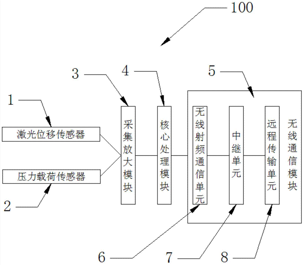
[0023] figure 1 It is a block diagram of a wireless dynamometer installed on the oil pumping unit based on laser ranging in an embodiment of the present invention and used to transmit data with a remote control center that draws dynamometer diagrams.

[0024] like figure 1 As shown, in this embodiment, the wireless dynamometer 100 installed on the pumping unit based on laser ranging and used for transmitting data with the remote control center that draws the dynamometer diagram includes: a laser displacement sensor 1, a pressure load sensor 2. Acquisition and amplification module 3 , core processing module 4 and wireless communication module 5 .

[0025] The wireless communication module 5 includes a wireless radio frequency communication unit 6 , a relay unit 7 and a remote transmission unit 8 .

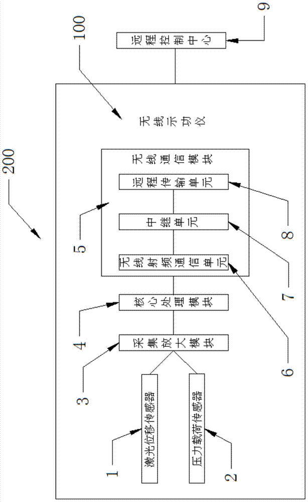
[0026] figure 2 It is a block diagram of a wireless dynamometer system in an embodiment of the present invention.

[0027] like figure 2 As shown, the wireless dynamometer ...


PUM


Abstract

The invention discloses a wireless indicator mounted on a pumping unit based on laser distance measurement for receiving and sending data with a remote control system for drawing indicator diagrams, a wireless indicator system and an indicator diagram measuring method thereof. The wireless indicator comprises a laser displacement sensor, a pressure load sensor, an acquiring amplification module, a core processing module and a wireless communication module, wherein the laser displacement sensor emits laser to measure the vertical displacement with the ground to output a displacement value. The wireless indicator of the invention directly measures the displacement by the laser displacement sensor, so that the influence from the vibration of the pumping unit is small, the precision of the indicator diagrams of the wireless indicator is improved, and the troubles of the existing indicators incapable of well measuring large stroke and under stroke of the pumping unit are solved. The wireless indicator system has at least one wireless indicator respectively mounted on different pumping units for respectively acquiring data of a plurality of oil wells to send to the remote control center to realize the area networking measurement.

Description

technical field [0001] The invention relates to a wireless dynamometer, in particular to a wireless dynamometer, a wireless dynamometer, and a wireless dynamometer based on laser ranging, which is installed on an oil pumping unit and used for sending data with a remote control center that draws a dynamometer diagram. Instrument system and its dynamometer measurement method. Background technique [0002] The wireless dynamometer is an instrument and equipment used to test the load and stroke of the oil well pumping unit and calculate the dynamometer diagram representing the working condition of the pumping unit. [0003] The principle block diagram of the wireless dynamometer for pumping units currently on the market is as follows: image 3 As shown, it consists of acceleration sensor, pressure load sensor, acquisition and amplification module, core processing module, wireless communication unit and external upper-layer equipment. The specific workflow is as follows: after t...

Claims


Application Information

Patent Timeline
Patent Type & Authority Applications(China)
IPC IPC(8): E21B47/009E21B47/12E21B43/00
Inventor 张学典潘丽娜于西龙李荆轩常敏董世坤初昀
Owner UNIV OF SHANGHAI FOR SCI & TECH
Why Eureka
Try Eureka