
a screen

A technology of sieve mesh and sieve mesh plate, which is applied in the direction of filter sieve, solid separation, grille, etc., can solve the problems of no large development, material hanging and blocking, etc., and achieve easy processing, simple process, and reduced broken The effect of the possibility of film hanging material blocking

Active Publication Date: 2016-08-03
GENOX RECYCLING TECH
View PDF6 Cites 0 Cited by
  • Summary
  • Abstract
  • Description
  • Claims
  • Application Information

AI Technical Summary

Problems solved by technology

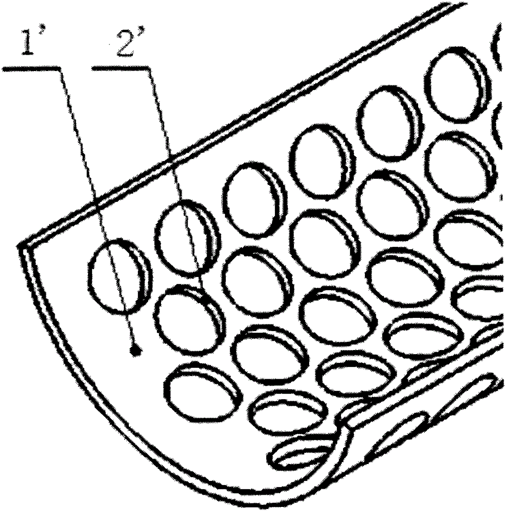
[0002] Currently, if figure 1 As shown, it is a structural schematic diagram of the existing screen, which is composed of a smooth surface 1' of a screen plate and a screen hole 2'. The screen hole 2' is generally a circular hole, a rhombus hole and a cross-shaped hole. In the environmental protection equipment manufacturing industry, the screen has become an indispensable and important part, but related technologies such as screen blockage, material jam, and material hanging have not been greatly developed for many years, even if a large number of screen holes are changed. The size and shape of the screen also has the following problems: the diamond-shaped hole and the cross-shaped hole screen are more smooth than the circular hole screen, and the output can be appropriately increased, but the broken film is irregular. In the form of spilling, there is still the possibility of material hanging and blocking
Nowadays, almost all the sieve plate surfaces of the screens in this field are still flat blocking materials, and there is no improvement from the surface of the sieve plate.

Method used


Image

  • a screen
  • a screen

Examples


Embodiment Construction

[0009] The present invention will be described in detail below in conjunction with the accompanying drawings and embodiments.

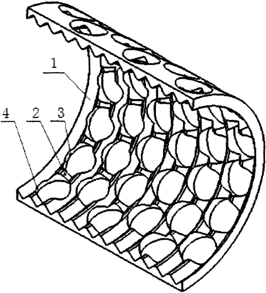
[0010] Such as figure 2 As shown, it is a structural schematic diagram of a screen of the present invention, which is provided with a screen plate 1, and the array of said screen plate 1 is provided with a plurality of V-shaped cone surfaces 2 and a plurality of screen holes 3, so that The edge of the screen hole 3 is an intersecting arc surface 4 , and the intersecting arc surface 4 is arranged on the V-shaped conical surface 2 .

[0011] When processing a screen of the present invention, the screen plate pipe material is first cut into a required arc shape, and after punching, the workpiece only needs to be placed on a lathe for lathe processing, and the shape of the screen of the invention can be turned.

[0012] The screen of the present invention does not change the shape and size of the screen hole 2 under the premise that the quality of the c...


PUM


Abstract

A screen of the present invention is provided with a screen plate, and the screen plate is provided with a plurality of V-shaped cone surfaces and a plurality of screen holes in an array, and the edges of the screen holes are intersecting arc surfaces. , the intersecting arc surface is set on the V-shaped tapered surface.

Description

technical field [0001] The invention relates to a screen for film filtration after the film is shredded by a single-shaft shredder, and in particular to a screen for more reliable and smooth feeding of the shredded film in the same aperture. Background technique [0002] Currently, if figure 1 As shown, it is a structural schematic diagram of the existing screen, which is composed of a smooth surface 1' of a screen plate and a screen hole 2'. The screen hole 2' is generally a circular hole, a diamond hole and a cross-shaped hole. In the environmental protection equipment manufacturing industry, the screen has become an indispensable and important part, but related technologies such as screen blockage, material jam, and material hanging have not been greatly developed for many years, even if a large number of screen holes are changed. The size and shape of the screen also has the following problems: the diamond-shaped hole and the cross-shaped hole screen are more smooth tha...

Claims


Application Information

Patent Timeline
Patent Type & Authority Patents(China)
IPC IPC(8): B07B1/46
Inventor 蒋经发
Owner GENOX RECYCLING TECH
Learn More