
Solvent oil fractionating tower pressure stability control and tail gas utilization device

A voltage stabilization control and fractionation column technology, applied in the direction of distillation adjustment/control, can solve problems such as increased energy consumption, unfavorable fractionation control, impact on fractionation efficiency and product quality control, and achieve easy operation and control, product quality, and The effect of making full use of

Inactive Publication Date: 2015-03-18
CHANGLE DERUN CHEM
View PDF3 Cites 0 Cited by
  • Summary
  • Abstract
  • Description
  • Claims
  • Application Information

AI Technical Summary

Problems solved by technology

The increase in the pressure of the fractionation tower system not only leads to an increase in the fractionation temperature and energy consumption, but also directly affects the fractionation efficiency and product quality control
In order to reduce the impact of the increase in the internal pressure of the finished product tank on the fractionation, only the method of venting and emptying can be used for decompression. On the one hand, the system pressure will be unstable, which is not conducive to the fractionation control; on the other hand, the non-condensable gas has not been fully utilized. , also pollute the environment

Method used


Image

  • Solvent oil fractionating tower pressure stability control and tail gas utilization device
  • Solvent oil fractionating tower pressure stability control and tail gas utilization device

Examples


Embodiment Construction

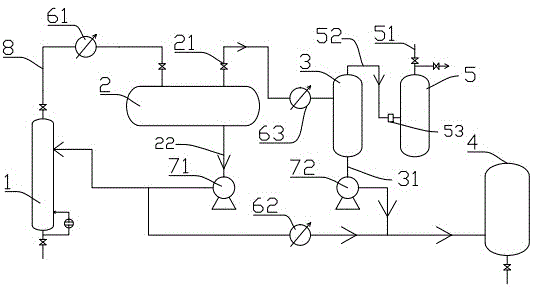
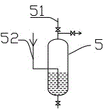
[0011] With reference to the accompanying drawings, the solvent oil fractionation tower pressure stabilization control and tail gas utilization device includes a fractionation tower 1, the bottom of the fractionation tower 1 is provided with a reboiler for fractionation heating, and the top of the fractionation tower 1 is connected in series with a first condenser 61 through a pipeline 8, A reflux tank 2 is connected to the rear end of the condenser. The upper and lower ends of the reflux tank 2 are respectively provided with a gas phase outlet 21 and a liquid phase outlet 22. The liquid phase outlet 22 is connected with a first delivery pump 71. A part of the output liquid of the delivery pump is refluxed to the fractionation tower 1, and the other part is condensed through the second condensate. After the device 62 cools down, it enters the storage tank. The rear end of the gas phase outlet 21 is connected with a fractionation pressure regulating device, and the fractionatio...


PUM


Abstract

The invention discloses a solvent oil fractionating tower pressure stability control and tail gas utilization device. The solvent oil fractionating tower pressure stability control and tail gas utilization device comprises a fractionating tower, a reflux tank and a storage tank which are connected in sequence through pipelines, wherein a first condenser is arranged between the fractionating tower and the reflux tank; a first conveying pump and a second condenser are arranged between the reflux tank and the storage tank; the output end of the first conveying pump is communicated with the fractionating tower and the storage tank; the reflux tank is provided with a fractionating pressure regulating device; the fractionating pressuring regulating device comprises a shunting condenser, an oil-gas separating tank and an isolating pressure relief tank. A gas-phase component inside the reflux tank enters the oil-gas separating tank after further cooling; the gas-phase component after the oil-gas separation enters the isolating pressure relief tank, is discharged into a boiler combustion chamber to be used as fuel, and does not enter a finished product storage tank any longer; the system pressure is not influenced when the liquid level inside the finished product storage tank is varied; assuredly, the pressure of the fractionating tower is not raised due to raising of the liquid level; the pressure of a fractionating system is stable; moreover, after isolating pressure relief, the fractionating pressure is small, the energy consumption is small, and the device is beneficial to energy saving and consumption reducing.

Description

technical field [0001] The invention belongs to the technical field of solvent oil fractionation devices, in particular to a solvent oil fractionation device with the function of dividing flow and regulating pressure. Background technique [0002] The fractionation unit for the production of solvent oil by atmospheric fractionation generally includes a fractionation tower, a cooler and a reflux tank. After the preheated naphtha enters the fractionation tower, it is heated at the bottom of the tower by a reboiler, and the product is separated and extracted by heating and reflux at a certain temperature and pressure. The gas phase product is exported from the top of the fractionation tower, and after being cooled by the primary condenser, the gas-liquid mixture enters the top reflux tank, and part of the liquid phase product is refluxed to the fractionation tower through the reflux pump, and the other part is input into the Finished cans. The gas phase in the reflux tank is ...

Claims


Application Information

Patent Timeline
Patent Type & Authority Patents(China)
IPC IPC(8): B01D3/42
Inventor 王玉军
Owner CHANGLE DERUN CHEM
Learn More