
Vision testing device with enhanced image clarity

A technology for image clarity and visual inspection, applied in image enhancement, image analysis, measuring devices, etc., can solve the problems of inconvenient maintenance, increase in type, size and weight, etc., and achieve the effect of improving the uniformity of light

Inactive Publication Date: 2014-02-05
MIRTEC
View PDF5 Cites 6 Cited by
  • Summary
  • Abstract
  • Description
  • Claims
  • Application Information

AI Technical Summary

Problems solved by technology

In this way, the types, sizes, and weights of the overall components housed in the housing with the above-mentioned central camera unit are increased, which brings inconvenience to maintenance.

Method used


Image

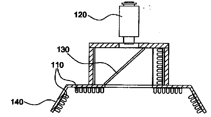
  • Vision testing device with enhanced image clarity
  • Vision testing device with enhanced image clarity
  • Vision testing device with enhanced image clarity

Examples


Embodiment Construction

[0033] Hereinafter, the configuration of the present invention will be described in detail with reference to the accompanying drawings.

[0034] Before the description, it needs to be explained that the terms used in this specification and claims are not limited to the meanings explained in the dictionary, and the inventor can properly define the concept of the term in order to better explain his invention. Therefore, The meanings or concepts of relevant terms shall be interpreted in accordance with the principle of conforming to the technical idea of ​​the present invention.

[0035] Therefore, the embodiments described in this specification and the structures marked in the drawings are only preferred embodiments of the present invention, and cannot fully embody the technical idea of ​​the present invention. Therefore, various changes or modifications can be made to the present application.

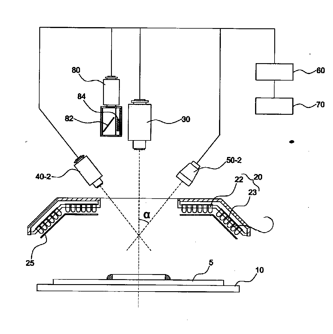
[0036] figure 2 is a schematic side view of a visual inspection device according ...


PUM


Abstract

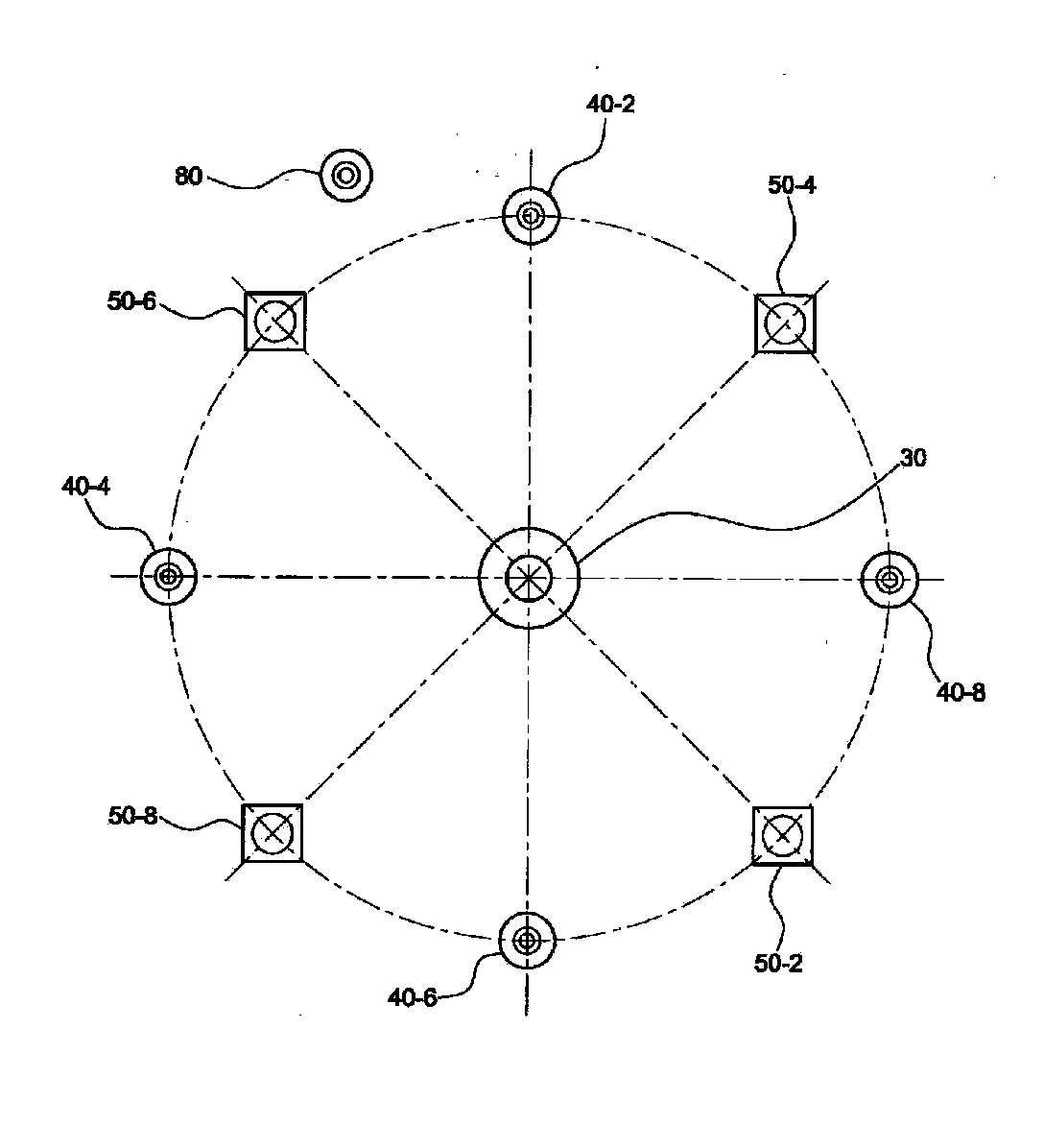
The vision testing device of the present invention is a vision testing device with enhanced image clarity for discriminating a satisfactory or a non-satisfactory testing object by shooting a testing object assembled or mounted during a component assembly process, and comparing the image taken with a previously inputted target image, and comprises: a stage part for fixing or transferring the testing object to the testing location; a lighting part located on the upper portion of the stage part, for providing lighting to the testing object; a first camera part located in the center of the lighting part, for obtaining a 2-dimensional image of the testing object; a second camera part placed in plurality on the side of the first camera part; a grid pattern irradiating part placed between the camera of the second camera part and a camera; a vision processing unit for reading the image taken in the first camera part and the second camera part, and discriminating whether the testing object is satisfactory or non-satisfactory; a control unit for controlling the stage part, the light irradiating part, and the first and the second camera parts; and a light diffusion part. The present invention enhances the uniformity of light being irradiated on the surface of the testing object. In addition, the present invention enables a more clear shooting of an image by removing a half mirror placed on the front of a camera part in the center, and enables convenient maintenance by miniaturizing the size of the device and dispersing the configuration.

Description

technical field [0001] The present invention relates to a visual inspection device. Specifically, it relates to a method of using a light diffusion plate to improve the uniformity of light irradiating an inspection object, using a variety of grid stripes to inspect the height, and removing the half mirror arranged in front of the camera for photographing the inspection object to improve image clarity. Visually inspect the device. Background technique [0002] In general, surface mount technology (SMT; Surface Mounting Technology) for assembling surface mount components such as printed circuit boards (PCBs) includes: technologies for miniaturization / integration of surface mount components (SMD; Surface Mounting Device) , The development of precision assembly equipment for the precise assembly of the above-mentioned surface mount components and the technology of using various assembly equipment. [0003] The surface mount production line consists of equipment such as surface...

Claims


Application Information

Patent Timeline
Patent Type & Authority Applications(China)
IPC IPC(8): G01N21/88G01B11/25
CPCG01B11/0608G01N21/95684G06T7/0004G01N2021/95638G06T2207/30141G01B11/2513H05K13/0815
Inventor 朴赞化吴尚珉金圣铉具滋明
Owner MIRTEC
Learn More