Method and device for finding ground fault in non-injection DC system
A DC system and ground fault technology, applied to fault locations, measuring devices, instruments, etc., can solve the problems of slow search speed, heavy workload, and inability to accurately find the fault point of the ground fault, achieving the effect of reducing running time
- Summary
- Abstract
- Description
- Claims
- Application Information
AI Technical Summary
Problems solved by technology
Method used
Image
Examples
Embodiment 1
[0051] This embodiment is an embodiment for measuring the insulation resistance of a DC system.
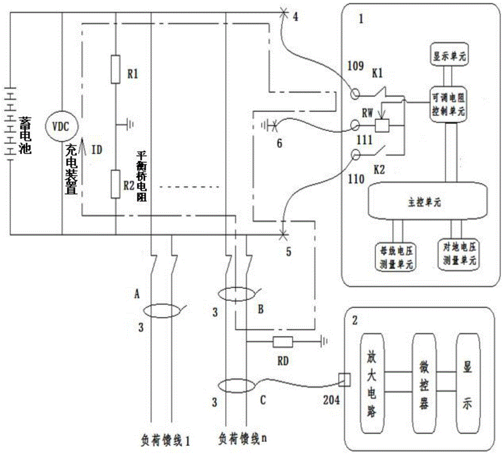
[0052] Reference Figure 4 , The grounding signal generation and control unit measures the voltage to ground of the DC system through the switch K1 and K2, and then calculates the insulation resistance R+ and R- of the positive and negative poles of the DC system according to the measured voltage to ground.
[0053] Reference Figure 5 . The ground signal generation and control unit transforms the DC system bus voltage and ground voltage into a 0~5V low voltage through a resistor divider, and inputs them to the bus voltage measurement unit and the ground voltage measurement unit respectively. The measured value of the ground voltage is used to calculate the positive and negative insulation resistance. The measured value of the bus voltage is used to judge whether the bus voltage of the DC system meets the operating requirements.
[0054] According to the insulation resistance of the po...
Embodiment 2
[0056] This embodiment is an embodiment for measuring the power frequency AC voltage in the DC system's ground voltage.
[0057] Reference Figure 5 , The grounding signal generation and control unit uses capacitors to separate and divide the voltage through resistors to sample the power frequency AC voltage in the DC system bus-to-ground voltage and input it to the bus-to-ground AC voltage measurement unit.
[0058] According to the value of the power frequency AC voltage in the ground voltage of the DC system to the ground, it can be judged whether the DC system has an AC intrusion into the DC system ground fault.
Embodiment 3
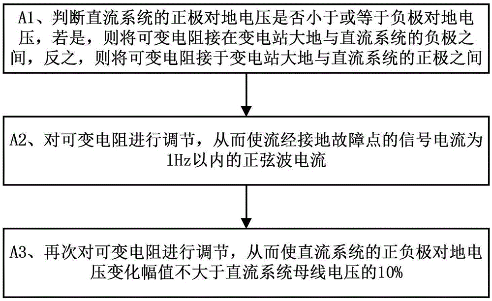
[0060] This embodiment is an embodiment for generating a ground signal current.
[0061] Reference Image 6 , The ground signal generation and control unit, through the variable resistance control unit, controls the variable resistance RW, so that the DC system ground voltage V+, V- changes in a sinusoidal manner.
[0062] When the DC system ground voltage V+ and V- change in a sine wave manner, sine wave ground signal currents IR+, IR- will be generated in the positive and negative grounding resistances R+, R-, and the positive and negative ground capacitance C+, C- produces sine wave ground signal current IC+, IC-.
[0063] Among them, the phase of the sine wave ground signal current in the grounding resistance and the sine wave ground signal current in the ground capacitance differ by 90°. The present invention uses this feature to distinguish whether the ground signal current in the feeder branch of the DC system is a resistive current or a capacitive current, thereby avoiding ...
PUM
 Abstract
Description
Claims
Application Information
 - R&D
- Intellectual Property
- Life Sciences
- Materials
- Tech Scout
- Unparalleled Data Quality
- Higher Quality Content
- 60% Fewer Hallucinations
Browse by: Latest US Patents, China's latest patents, Technical Efficacy Thesaurus, Application Domain, Technology Topic, Popular Technical Reports.
© 2025 PatSnap. All rights reserved.Legal|Privacy policy|Modern Slavery Act Transparency Statement|Sitemap|About US| Contact US: help@patsnap.com


