Optical method based high-speed aircraft hot surface full-field deformation measuring device

A high-speed aircraft and optical method technology, which is applied in the field of full-field deformation measurement of the thermal surface of high-speed aircraft, can solve problems such as aliasing interference of high-temperature light sources, and achieve good test results.

Inactive Publication Date: 2014-02-05
BEIHANG UNIV
View PDF4 Cites 29 Cited by
  • Summary
  • Abstract
  • Description
  • Claims
  • Application Information

AI Technical Summary

Problems solved by technology

As a result, the intensity of light emitted by the infrared radiation heat source array is greater than that emitted by the heated body, so the problem of aliasing interference caused by high-temperature light sources must be solved
Due to the above reasons, so far, there have been no relevant reports in the domestic and foreign literature on the successful measurement of the thermal surface deformation of high-speed aircraft structures using optical measurement methods in a high-temperature thermal radiation environment.

Method used


Image

  • Optical method based high-speed aircraft hot surface full-field deformation measuring device
  • Optical method based high-speed aircraft hot surface full-field deformation measuring device
  • Optical method based high-speed aircraft hot surface full-field deformation measuring device

Examples


Embodiment Construction

[0031] The present invention will be further described below in conjunction with the accompanying drawings and specific embodiments.

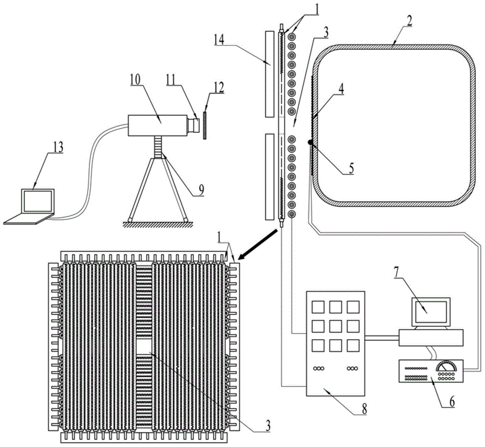
[0032] like figure 1 As shown, the present invention consists of a double-layer quartz lamp heating array 1, a high-speed aircraft thin-walled shell 2, a square light-transmitting window 3, speckle particles 4, a thermocouple sensor 5, a signal amplifier 6, a temperature control computer 7, a driving power supply 8, The adjustment bracket 9, the CMOS camera 10, the lens 11, the narrow bandpass optical filter 12, the image processing computer 13 and the light high temperature ceramic plate 14 are composed. The infrared radiant light emitted by the double-layer quartz lamp heating array 1 irradiates the surface of the thin-walled shell 2 of the high-speed aircraft to simulate the thermal environment in flight, and the thermocouple sensor 5 is installed on the surface of the thin-walled shell 2 of the high-speed aircraft, and the thermocouple sens...


PUM


Abstract

The invention provides an optical method based high-speed aircraft hot surface full-field deformation measuring device. The optical method based high-speed aircraft hot surface full-field deformation measuring device comprises a double-layer quartz lamp heating array, a thin-wall high-speed aircraft shell, a square transparent window, speckle particles, a thermocouple sensor, a signal amplifier, a temperature control computer, a driving power supply, a CMOS (Complementary Metal Oxide Semiconductor) camera, a lens, a narrow-band-pass optical filter and an image processing computer. In order to solve the problem of signal blockage caused by a high temperature radiant heat source between the CMOS camera and the surface of the high-speed aircraft shell, the vertical double-layer quartz lamp heating array is designed and the square transparent window with small area is formed, so that the optical camera lens can obtain images of the hot surface of the high-speed aircraft through the transparent window. The interference light ray of the quartz lamp heating array is shielded by selecting the narrow-band-pass optical filter with specific wave length, so that speckle images with high quality and no degeneration on the hot surface of the high-speed aircraft is obtained; a digital image correlation method is utilized for analyzing the speckle images under different temperatures to realize full measurement on the displacement field and the strain field of the hot surface of the high-speed aircraft in a high temperature environment.

Description

technical field [0001] The invention relates to an optical method-based full-field deformation measurement device for a hot surface of a high-speed aircraft. Especially when conducting thermal strength tests of high-speed aircraft such as missiles, non-contact optical methods can be used to measure the full-field deformation of the front surface of high-speed aircraft. It provides an important test method for thermal strength analysis and safety and reliability design of high-speed missiles and high-speed aerospace vehicles. Background technique [0002] Hypersonic aircraft can achieve global long-distance and rapid arrival, implement effective high-altitude and high-speed penetration, and complete rapid and precise strikes. Due to its extremely important military application value and great strategic significance, hypersonic vehicles have become the focus of research by major aerospace powers in the world. [0003] In order to achieve the strategic goal of quickly reachin...

Claims


Application Information

Patent Timeline
IPC IPC(8): G01N25/00G01B11/16G01B11/02
Inventor 潘兵吴大方俞立平王岳武王杰蒲颖
Owner BEIHANG UNIV
Why Eureka
Try Eureka