
A variable displacement oil pump control mechanism

A technology of displacement machines and oil pumps, which is applied to lubricating pumps, mechanical equipment, engine components, etc. It can solve the problems of increased oil pressure in engine oil passages, increased oil volume at friction parts, and increased costs, and achieves variable displacement and additional Less friction and less power consumption

Active Publication Date: 2016-02-24
ZHEJIANG GEELY HLDG GRP CO LTD +1
View PDF7 Cites 0 Cited by
  • Summary
  • Abstract
  • Description
  • Claims
  • Application Information

AI Technical Summary

Problems solved by technology

There are some disadvantages in this way: that is, the lubrication of some parts of the engine does not need to increase the lubricating oil with the increase of the engine speed. This will increase the oil pressure in the engine oil passage, increase the oil volume of the friction parts, and the temperature is too low, which will affect the lubrication. effect, while increasing the friction loss
Although this structure can change the displacement of the oil pump, this structure needs to install an oil pressure sensor that generates a pressure signal, and a controller connected to the oil pressure sensor needs to be installed to operate and control the flow of the oil pump through the function of the pressure signal
Such a structure is too complicated and too many electronic components also cause excessive load on the engine and increase the cost

Method used


Image

  • A variable displacement oil pump control mechanism
  • A variable displacement oil pump control mechanism
  • A variable displacement oil pump control mechanism

Examples


Embodiment Construction

[0035] The present invention will be further described below in conjunction with the embodiments shown in the accompanying drawings.

[0036] like figure 1 As shown, a variable displacement oil pump control mechanism includes a transmission shaft 1, an outer rotor 2 connected in sequence via the transmission shaft 1, an inner rotor 3, a push plate 4 and a balance weight guide plate 5, which are installed on the balance weight guide plate 5 Two groups of balance weights 6 on the right side, rivets 7, pins 8, rocker arms 9, pin shafts 10.

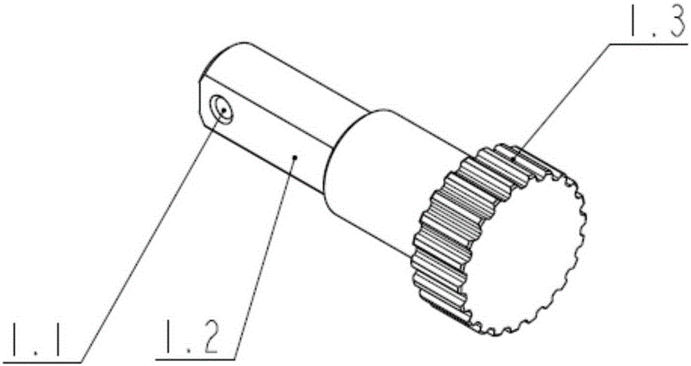
[0037] like figure 2 As shown, the transmission shaft 1 includes an external spline 1.3 on one side and a guide transmission rod 1.2 on the other side. At least one pin hole 1.1 is provided at the end of the guide transmission rod 1.2. In this embodiment, the guide transmission rod 1.2 is a flat square transmission rod. There is a pin hole 1.1 at the end of the guide transmission rod 1.2. The guide transmission rod 1.2 passes through the i...


PUM


Abstract

A variable displacement oil pump regulation mechanism comprises a transmission shaft, an outer rotor, an inner rotor, a push plate, a balance block guide plate, two groups of balance blocks, rivets, swing arms and pin shafts, wherein the outer rotor, the inner rotor, the push plate and the balance block guide plate are sequentially and serially connected by the transmission shaft, and the two groups of balance blocks are mounted on the right side of the balance block guide plate. The balance block guide plate is mounted on a guide transmission rod of the transmission shaft, the transmission guide rod drives the balance block guide plate to rotate, the balance block guide plate can axially move along the transmission shaft, the balance blocks are mounted on the balance block guide plate through the rivets and can move along the rivets in the direction far away from the center of the balance block guide plate, the swing arms are mounted on the balance blocks through pin holes and pins and mounted on the pin shafts through pin shaft holes, the pin shafts are mounted in the pin shaft holes of the transmission shaft, and the balance blocks push the transmission shaft to drive the inner rotor and the push plate to move rightwards when centrifugally moving. The variable displacement oil pump regulation mechanism is controlled to work by the aid of the centrifugal force of the balance blocks and the lever principle, the displacement of an oil pump can be changed, additional friction is less, and power consumption of an engine is low.

Description

technical field [0001] The invention relates to a variable displacement engine oil pump, in particular to a variable displacement engine oil pump regulating mechanism. Background technique [0002] At present, the oil pumps used in automotive internal combustion engines are generally fixed-displacement oil pumps, and the oil flow is proportional to the engine speed. The flow of this type of oil pump increases continuously with the increase of the engine speed. For a specific internal combustion engine, designers usually choose a large-displacement oil pump under the worst working conditions, that is, the oil pump corresponds to the low engine speed after determining the displacement, so that as the engine speed increases, the oil pump will The displacement of the oil pump increases accordingly. There are some disadvantages in this way: that is, the lubrication of some parts of the engine does not need to increase the lubricating oil with the increase of the engine speed. Th...

Claims


Application Information

Patent Timeline
Patent Type & Authority Patents(China)
IPC IPC(8): F16N13/04
Inventor 白广松袁爽由毅沈源冯擎峰
Owner ZHEJIANG GEELY HLDG GRP CO LTD
Learn More