
Diaphragm installation device

A technology for installing devices and diaphragms, applied in metal processing, metal processing equipment, hand-held tools, etc., can solve the problems of complex installation actions, large space occupation, and low production efficiency of backlight modules

Active Publication Date: 2014-02-05
BOE TECH GRP CO LTD +1
View PDF6 Cites 20 Cited by
  • Summary
  • Abstract
  • Description
  • Claims
  • Application Information

AI Technical Summary

Problems solved by technology

Because the diaphragm is relatively thin, when installing, it is necessary to insert the insertion side of the diaphragm into the gap between the plastic frame and the back plate, and then place the entire diaphragm. The installation action is more complicated. Therefore, at this stage, manual to assemble the diaphragm
[0003] The disadvantage of the existing technology is that the backlight module needs to be composed of four films attached during assembly, and most of the films are in the form of sheets. During manual assembly, various films need to be arranged and placed on the workbench in advance , takes up a lot of space, and at the same time, the efficiency of manual installation is relatively low, which in turn causes the production efficiency of the entire backlight module to be relatively low

Method used


Image

  • Diaphragm installation device
  • Diaphragm installation device
  • Diaphragm installation device

Examples


Embodiment 1

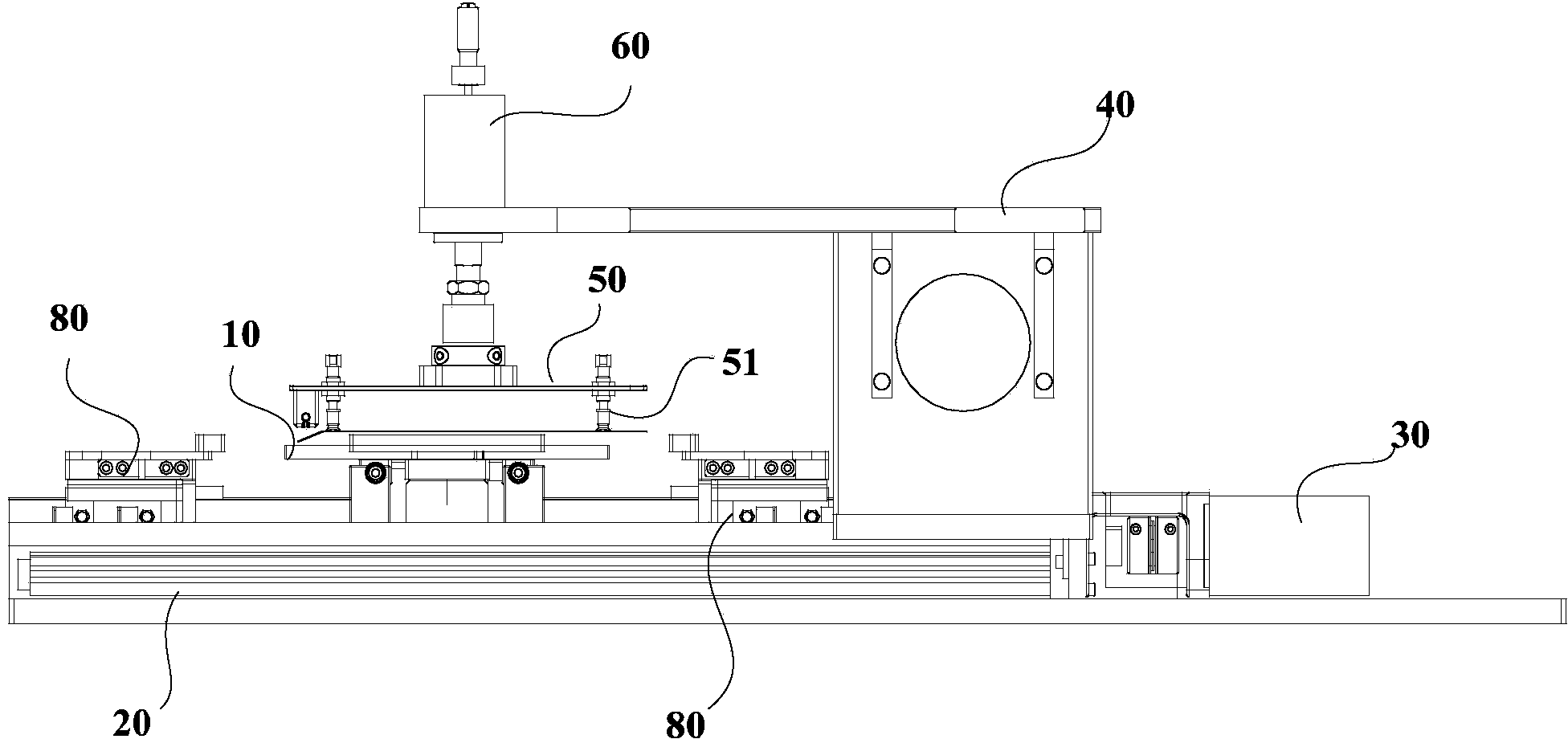
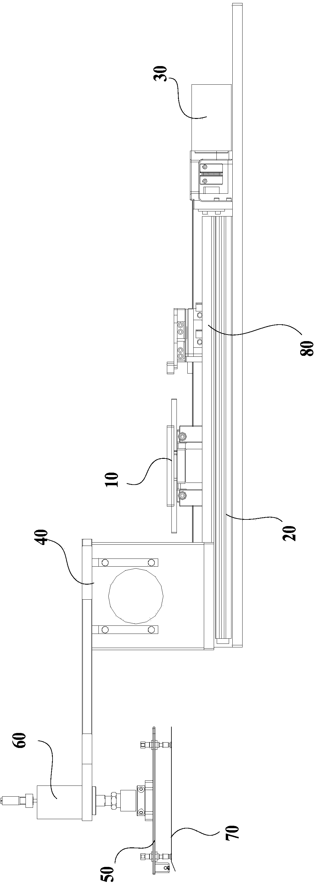
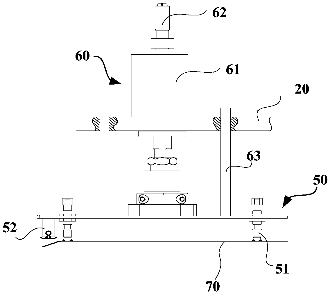
[0046] continue to refer image 3 , the lifting device 60 is a hydraulic cylinder or a cylinder 61, wherein the cylinder body of the cylinder 61 or the hydraulic cylinder is fixed on the support base 40, the connecting rod of the cylinder 61 or the hydraulic cylinder is fixedly connected with the suction cup device 50, and the cylinder 61 is pushed by air pressure or hydraulic pressure Or the connecting rod of the hydraulic cylinder, so as to realize the rise or fall of the suction cup device 50. During specific installation, the bottom of the cylinder body (the end away from the connecting rod) of the cylinder 61 can be fixed on the support base 40, or the One end of one end is fixed on the support seat 40, and the manufacturer can choose reasonably according to the size of the support seat 40, the height of the carrying device and the size of the air cylinder 61 or hydraulic cylinder during actual production.

[0047] When the air cylinder 61 or the hydraulic cylinder is use...

Embodiment 2

[0050] The lifting device 60 adopts a mechanical transmission mode. Specifically, the lifting device 60 includes: a rack slidably mounted on the support base 40 , and a motor fixed to the support base 40 , and the motor meshes with the rack through a gear.

[0051] At this time, one end of the rack is fixedly connected to the suction cup device 50 , and the other end is slidably assembled to the support seat 40 . Specifically, the support seat 40 has a protrusion, and the back side of the rack (the side opposite to the teeth) has a groove that is slidably fitted with the protrusion. And the lifting of the rack is controlled by the motor, thereby realizing the lifting of the sucker device 50 . Wherein, the motor can be a servo motor or a stepping motor, which has good controllability and motion stability.

[0052] In order to further improve the stability of the rack when moving, preferably, the support base 40 is provided with a through hole that is slidably fitted with the r...


PUM


Abstract

The invention relates to the technical field of manufacturing of liquid crystal display devices and discloses a diaphragm installation device. The diaphragm installation device comprises a carrying mechanism, a sliding rail, a mechanical arm, a driving device and a control device, wherein the mechanical arm is slidably assembled onto the sliding rail and is used for sucking and putting down a diaphragm; a sucking cup device of the mechanical arm is provided with sucking cups for sucking the diaphragm and a blowing device for bending the insertion side of the diaphragm; the driving device is used for driving the mechanical arm to slide; the control device is used for controlling the mechanical arm and the driving device. The diaphragm installation device has the beneficial effects that the diaphragm is moved by the mechanical arm, is sucked by the sucking cups and the blowing device of the sucking cup device and is bent, and the bent diaphragm can be inserted into a plastic frame; meanwhile, each execution motion is carried out through the control device, automation is realized, and the production efficiency of a backlight module is improved.

Description

technical field [0001] The invention relates to the technical field of manufacturing liquid crystal display devices, in particular to a diaphragm installation device. Background technique [0002] With the development of thinner liquid crystal display devices, the production process of each component of the liquid crystal display device has changed accordingly. Taking the backlight module industry as an example, in the previous production process, the film is placed first, and then the plastic frame is set on the outside of the film, and the film is fixed. With the development of thinner liquid crystal display devices, the production method of the backlight module has changed to: first fix the plastic frame on the back plate of the backlight module, then put the film into the plastic frame, and put the film One side is inserted between the plastic frame and the backplane for fixing. Because the diaphragm is relatively thin, when installing, it is necessary to insert the in...

Claims


Application Information

Patent Timeline
IPC IPC(8): B23P19/04
CPCB25B27/00
Inventor 曹春雷武冰
Owner BOE TECH GRP CO LTD
Learn More