Fixing device for medical apparatuses and instruments
A technology for medical devices and locking arms, applied in the direction of electrodes, internal electrodes, etc., can solve the problems of horizontal or vertical displacement of electrodes, poor effect, large electrode positioning errors, etc.
- Summary
- Abstract
- Description
- Claims
- Application Information
AI Technical Summary
Problems solved by technology
Method used
Image
Examples
Embodiment approach 1
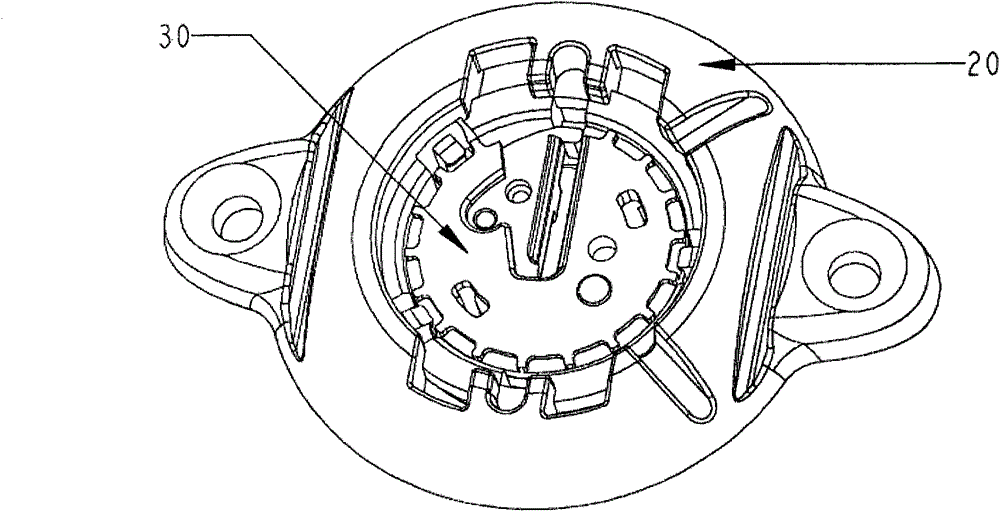
[0040] as attached figure 1 To attach Figure 14 As shown, an electrode wire fixing device 10 includes: a bone hole base 20 , a locking component 30 , a bone hole cover 40 , and a placement handle 50 . Wherein the locking component 30 further includes: a locking upper cover 301 , a locking arm 302 , and a locking lower cover 303 . The storage handle 50 is made of the same two pieces of cards that are used together during use.
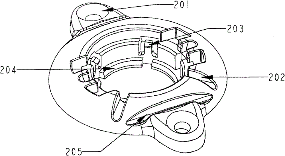
[0041] During the use of the present invention, the bone hole base 20 is fixed at the position of the skull hole through the characteristic screw hole 201 and the skull screw. During the screw fixation process, the bone hole base 20 has a feature 205 that adapts to the deformation of the fixing surface. The specific fixing process is mainly described in the present invention. It is completed by the cooperation of the bone hole base 20 and the placing handle 50, and the placing handle 50 combines the two pieces together through the engaging feature 504...
Embodiment approach 2
[0047] as attached Figure 15 to attach Figure 17 As shown, the difference from Embodiment 1 is the action mode of the locking member 30 . In this embodiment, the locking arm 322 is composed of two parts, namely a rotating arm 3221 and a clamping arm 3222 . The rotating arm 3221 moves in an arc along the track feature 3231. The rotating arm 3221 and the clamping arm 3222 are connected to the boss 32222 through the groove 32211. Lateral displacement movement, thus the arc movement of the rotating arm 3221 pushes the clamping arm 3222 to produce lateral displacement movement, the structure is as attached Figure 15 with attached Figure 17 shown.
[0048] After the locking arm reaches the specified position, the elastic arm feature 3232 and the rotating arm feature 32212 are engaged with each other, such as Figure 16 , Figure 17 As shown, the locking arm is fixed to realize the locking function.
Embodiment approach 3
[0050] as attached Figure 18 to attach Figure 20 As shown, what is different from Embodiment 1 is the action mode of the locking member 30. In this embodiment, the locking arm 302 is composed of two parts, which are respectively the inclined slider 3321 and the clamping arm 3322, as shown in the attached Figure 18 , attached Figure 20 shown. The specific implementation process is characterized by oblique movement of the oblique slider 3321, and the clamping arm 3322 is restricted up and down in the locking upper shell. During the moving process, the contact surface with the clamping arm 3322 pushes the clamping arm to generate lateral movement, thereby forming a clamping electrode wire structure. After the locking arm reaches the designated position, the retracted stroke of the inclined slider 3321 is engaged, and the locking is completed.
PUM
 Abstract
Description
Claims
Application Information
 - R&D
- Intellectual Property
- Life Sciences
- Materials
- Tech Scout
- Unparalleled Data Quality
- Higher Quality Content
- 60% Fewer Hallucinations
Browse by: Latest US Patents, China's latest patents, Technical Efficacy Thesaurus, Application Domain, Technology Topic, Popular Technical Reports.
© 2025 PatSnap. All rights reserved.Legal|Privacy policy|Modern Slavery Act Transparency Statement|Sitemap|About US| Contact US: help@patsnap.com


