Method and device for non-contact measurement of surfaces

A non-contact measurement and measurand technology, applied in the direction of measurement device, geometric characteristic/aberration measurement, using optical device, etc., can solve problems such as discontinuity

Active Publication Date: 2017-06-13
UNIV POLITECNICA DE CATALUNYA
View PDF6 Cites 0 Cited by
  • Summary
  • Abstract
  • Description
  • Claims
  • Application Information

AI Technical Summary

Problems solved by technology

A further disadvantage is that these methods are discontinuous

Method used


Image

  • Method and device for non-contact measurement of surfaces
  • Method and device for non-contact measurement of surfaces
  • Method and device for non-contact measurement of surfaces

Examples


Embodiment Construction

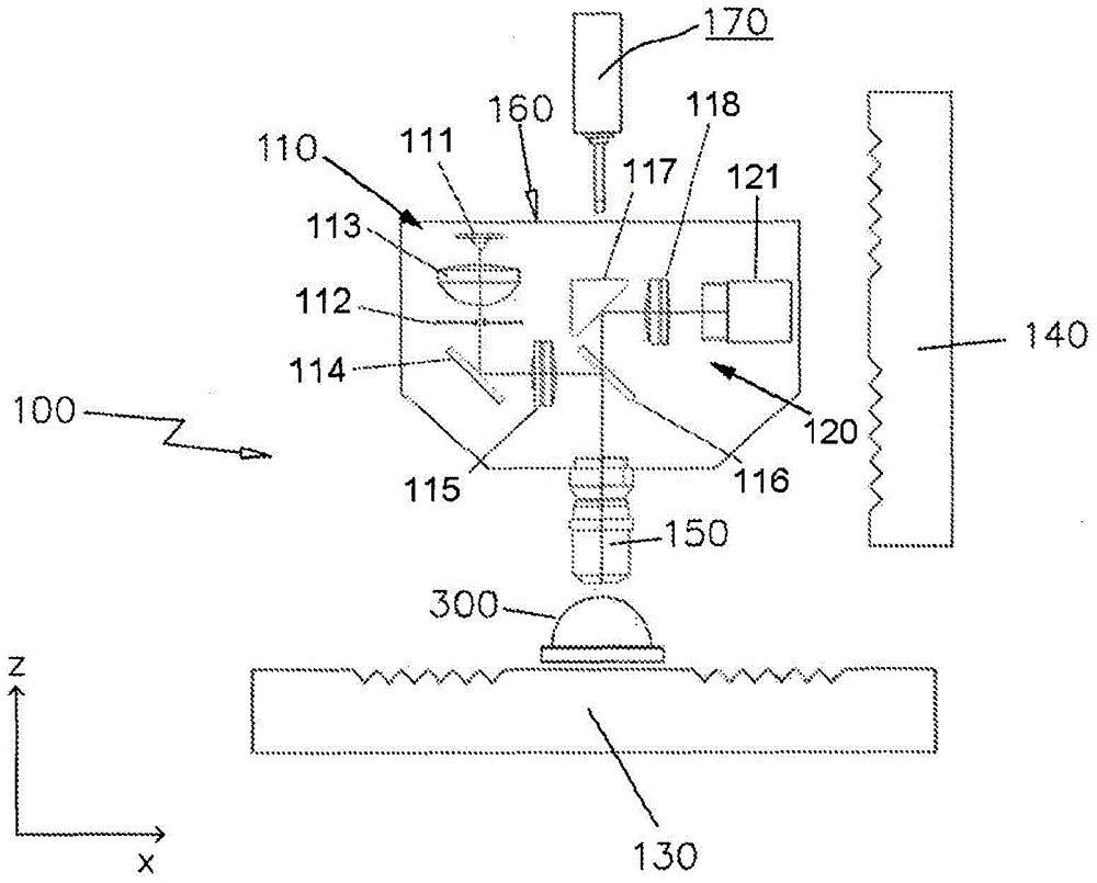
[0099] The drawings illustrate an exemplary embodiment of a non-contact, high-precision, rapid measurement device. figure 1 A non-limiting example of the device shown in is generally indicated by 100 . Optical profilers are capable of measuring any optical surface. While useful in many applications, the present example relates to a measurement device 100 for non-contact measurement of the surface of a lens. The lens is generally indicated at 300 in the drawings herein.

[0100]The measurement device 100 comprises a light projection arrangement 110 comprising one or a series of LEDs 111 . Such a light projection device 110 in the shown device 100 is suitable for projecting a pattern of structured light through an aperture 112 onto a target area of ​​the lens 300 . Such as figure 1 As shown in , the light projection device 110 further includes a collimating optics 113 , a 45° mirror 114 , an optical lens 115 , a beam splitter 116 and a microscope objective 150 .

[0101] Th...


PUM


Abstract

The present disclosure relates to methods and apparatus for non-contact measurement of surfaces. The slit (m) is projected onto the object surface with the reference point (X1) in the horizontal axis (x) closest to the optimum position (P) in the focus position. After reflecting the light containing said fiducial point (X1), an image of the field of view area (F) is acquired. The position (Z1) of the object (300) in the vertical axis (z) is determined. After reflecting the light with the reference point (X2, X3...Xn), by simultaneously moving the object (300) along the axis (z) to maintain the best position among the closest focus positions of the reference point (X2, X3...Xn) ( P), an image of the corresponding field of view area (F) is acquired. Determine the position (Z2,Z3...Zn) at which to acquire the image. An optimum position (P) among focus positions along the horizontal axis (x) is determined for each image. Correction differences (Δ1, Δ2 . . . Δn) between the optimum position (P) and the reference points (X1, X2 .. Xn) among the focus positions are calculated.

Description

technical field [0001] A method of non-contact surface metrology is disclosed herein. More specifically, a method for non-contact measurement of a surface is provided. [0002] Devices for non-contact measuring surfaces are also disclosed. Background technique [0003] Optical components with flat and spherical surfaces are relatively easy to manufacture and measure. However, due to their aberration-limited performance, the optical components with flat and spherical surfaces are replaced by optical components with complex surfaces, such as aspheric surfaces and arbitrary-form surfaces. Optical components with complex surfaces can eliminate aberrations and provide many other advantages. Optical components with complex surfaces are obtained using machining, light profiling and metrology techniques. [0004] In recent years, advanced manufacturing techniques for such optical components have been developed due to the need for machining of previously complex optical surfaces....

Claims


Application Information

Patent Timeline
Patent Type & Authority Patents(China)
IPC IPC(8): G01B11/25G02B21/00
CPCG01B11/2518G01M11/025G02B21/0016G02B21/06G01B9/04G01B11/25G01B11/24
Inventor F·拉古尔塔·伯特兰A·皮恩托·维拉R·阿蒂加斯·珀萨尔斯C·卡德瓦尔·阿蒂古埃斯
Owner UNIV POLITECNICA DE CATALUNYA
Why Eureka
Try Eureka