


Quick Research
Generate reliable direction feasibility study reports for your R&D in just a few steps.

Technical Q&A
Discover and master advanced knowledge NOW. Basics, ideas, possibilities, all at once.

Find Solutions
As an expert in R&D theories, this can generate solutions to your technical problems instantly.

Evaluate Feasibility
Analyze your overall solution with one click, know your potential R&D risks in advance.

Monitor Landscape
Get weekly tech updates, stay abreast of the latest tech innovations and key insights.
Method and device for compensating system time
A technology for system time and compensation equipment, applied in the field of communication, can solve the problems of inability to compensate the system time of 1588 equipment, and inability to measure the difference between system time and system time by a time comprehensive tester.
- Summary
- Abstract
- Description
- Claims
- Application Information
AI Technical Summary
Problems solved by technology
Method used
Image

Examples
Embodiment 1
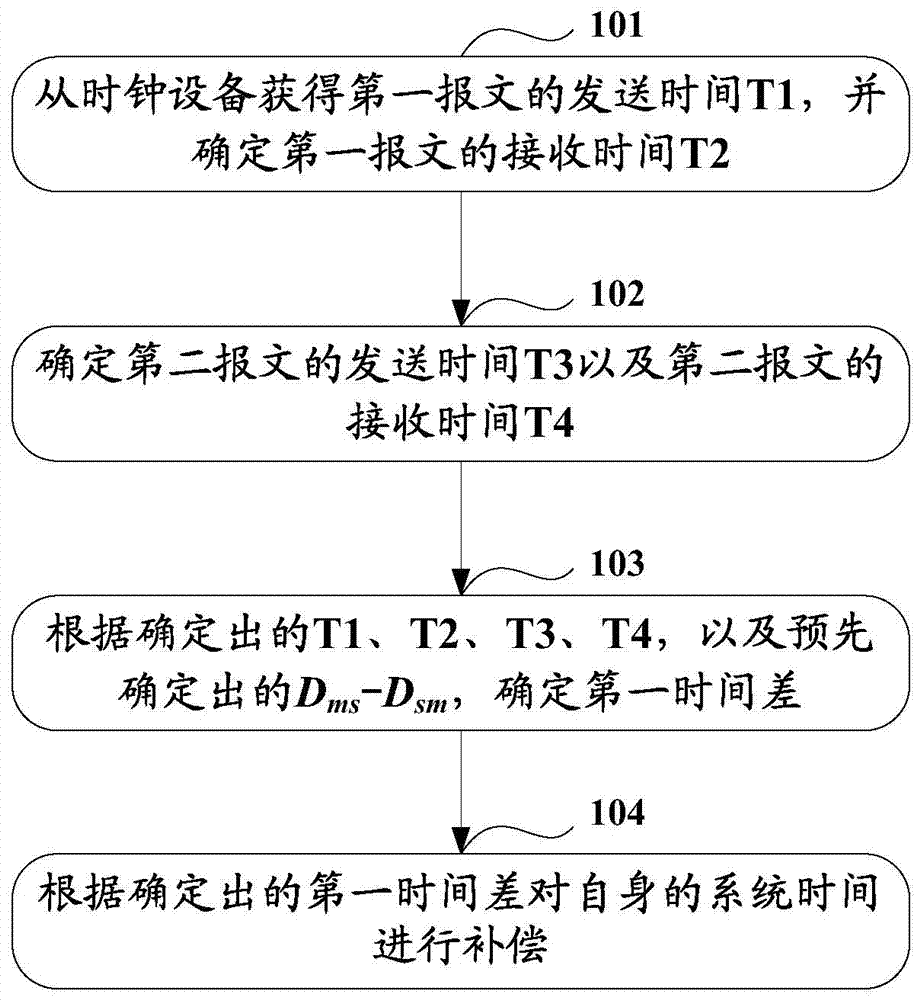
[0030] Such as figure 2 As shown, it is a schematic diagram of the steps of the system time compensation method in Embodiment 1 of the present invention. The method mainly includes the following steps:
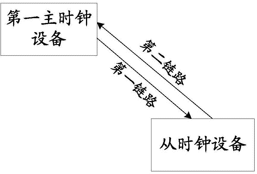
[0031] Step 101: The slave clock device receives the first message sent by the first master clock device through the first link, obtains the sending time T1 of the first message from the first message, and determines the receiving time of the first message T2.
[0032] The concrete realization mode of this step 101 can be:
[0033] The first master clock device sends a synchronous SYNC message to the slave clock device through the first link at time T1, and the SYNC message arrives at the slave clock device at time T2 after being transmitted through the first link. Wherein, the T1 time is specifically a time stamp, indicating the time when the first master clock device sends the SYNC message, which corresponds to the system time of the first master clock device, and the fir...
Embodiment 2
[0070] The second embodiment is a system time compensation device belonging to the same inventive concept as the first embodiment, such as Figure 5 As shown, the device includes: a first time determination module 11, a first time difference determination module 12, a compensation module 13, a second time determination module 14, a second time difference determination module 15 and a difference value determination module 16, wherein:
[0071] The first time determining module 11 is configured to determine the receiving time of the first message sent by the first master clock device received through the first link, the sending time of the first message included in the first message, the The system time compensation device sends the sending time of the second message to the first master clock device through the second link, and the receiving time of receiving the second message by the first master clock device.
[0072] The first time difference determining module 12 is used to ...
PUM
 Abstract
Description
Claims
Application Information
 - R&D Engineer
- R&D Manager
- IP Professional
- Industry Leading Data Capabilities
- Powerful AI technology
- Patent DNA Extraction
Browse by: Latest US Patents, China's latest patents, Technical Efficacy Thesaurus, Application Domain, Technology Topic, Popular Technical Reports.
© 2024 PatSnap. All rights reserved.Legal|Privacy policy|Modern Slavery Act Transparency Statement|Sitemap|About US| Contact US: help@patsnap.com