High-flow high-frequency-response digital valve capable of rotating and being controlled in parallel

A high-flow, high-frequency response technology, used in fluid pressure actuation devices, servo motor components, mechanical equipment, etc., can solve the problems of reducing engineering adaptability, limiting the frequency response of servo valves, and large flow gain. Flow and high-frequency response, strong engineering adaptability, and the effect of ensuring control accuracy

Active Publication Date: 2014-01-29
NANTONG METALFORMING EQUIP
View PDF9 Cites 10 Cited by
  • Summary
  • Abstract
  • Description
  • Claims
  • Application Information

AI Technical Summary

Problems solved by technology

However, as the rotation angle corresponding to each pulse becomes smaller, the number of steps required for the servo motor to rotate the same angle increases, which reduces the response speed of the spool and limits the further improvement of the frequency response of the servo valve under high precision conditions.
[0005] 2) The gain of the pilot stage driving the main stage needs to be improved
The unilateral gain control method currently used in this type of servo screw mechanism (for example, refer to patent 200910153014.6) fails to fully utilize the controllable area of ​​the spool and maximize the gain of the pilot stage driving the main stage to further improve the main valve. Response speed of core action
[0006] 3) The adaptability of the precise control of the terminal position needs to be strengthened
Since the servo valve is designed with both large flow and high frequency response, the flow gain is large, and it is difficult to achieve precise control at the end position of the servo system, which restricts its application in large composite material presses, friction welding machines and other equipment , which limits the improvement of its high-precision control performance and reduces the engineering adaptability of the valve

Method used


Image

  • High-flow high-frequency-response digital valve capable of rotating and being controlled in parallel
  • High-flow high-frequency-response digital valve capable of rotating and being controlled in parallel
  • High-flow high-frequency-response digital valve capable of rotating and being controlled in parallel

Examples


Embodiment Construction

[0032] The specific implementation of the present invention will be described below in conjunction with the drawings and examples.

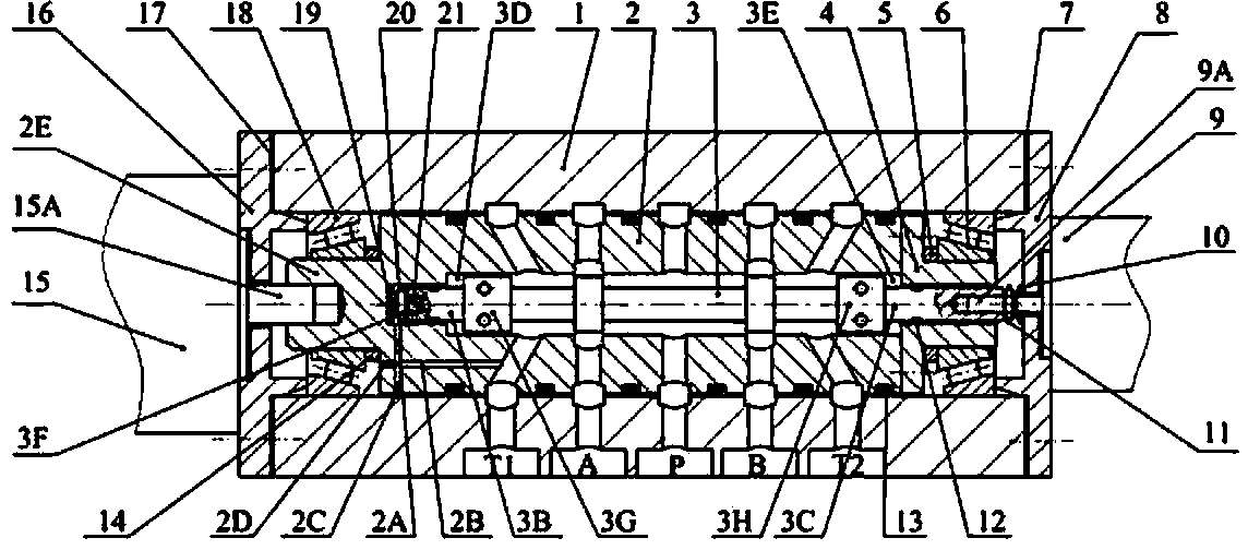
[0033] figure 1 A schematic diagram schematically showing the internal structure of an embodiment of the present invention.

[0034] A high-flow high-response digital valve that can be controlled in parallel with rotation, including a valve body 1, a valve sleeve 2, a valve core 3, a left servo motor 15, a right servo motor 9, a left end cover 16, and a right end cover 8; the valve sleeve 2 can be It is installed in the valve body 1 for rotation, and the valve core 3 is installed in the valve sleeve 2 for rotation.

[0035] The left servo motor 15 is installed on the valve body 1 through the left end cover 16, the left servo motor output shaft 15A is fixedly connected to the valve sleeve 2, the right servo motor 9 is installed on the valve body 1 through the right end cover 8, and the valve core 3 is connected to the right servo motor. Motor ou...


PUM


Abstract

The invention discloses a high-flow high-frequency-response digital valve capable of rotating and being controlled in parallel. The digital valve is composed of a valve body, a valve sleeve, a left servo motor, a right servo motor and the like. The valve sleeve is arranged in the valve body in a rotation mode, and a valve core is installed in the valve sleeve in a rotation mode. Valve holes for high-pressure oil or low-pressure oil to pass through are formed in two ends of a valve core shaft, the valve holes are matched with spiral grooves formed in corresponding positions on two sides of the valve sleeve, and axial moving of the valve core is achieved by controlling the pressure in cavities on the left side and the right side of the valve core. The right servo motor drives the valve core to rotate, the left servo motor drives the valve sleeve to rotate, bi-directional rotation is achieved through parallel control of the valve core and the valve sleeve, and frequency limit caused by the fact that only the valve core rotates in a traditional valve is broken through. Spiral groove mechanisms with different spiral lead angles are formed in the valve sleeve, valve core rotation is changed into the axial moving, and a function of multi-stage gaining is achieved. By means of parallel connection rotation and digital control of the valve core and the valve sleeve and by means of the spiral groove array structure with the multi-stage gaining function, high flow and high frequency response of the servo valve and precise control of a terminal position are achieved.

Description

technical field [0001] The invention relates to an electro-hydraulic servo valve in the field of fluid transmission and control, in particular to a high-frequency and large-flow digital servo valve that can be controlled in parallel. Background technique [0002] Electro-hydraulic servo systems are widely used in many fields such as aerospace, metallurgy, shipbuilding, and military heavy industry, and their core components are electro-hydraulic servo valves. The high-frequency response characteristics of electro-hydraulic servo valves significantly improve the control performance of high-end equipment (such as large composite material presses, friction welding machines, high-frequency electro-hydraulic vibration tables, electro-hydraulic servo steering gears, and space simulators, etc.). The traditional electro-hydraulic servo valve generally uses a pre-stage drive power slide valve stage, and the input signal is an analog signal. The poor anti-interference ability of the an...

Claims


Application Information

Patent Timeline
IPC IPC(8): F15B13/02
Inventor 杜恒郭凡马冲
Owner NANTONG METALFORMING EQUIP
Why Eureka
Try Eureka