Optical fiber type on-line real-time pantograph lifting pressure detection system

A technology of pantograph and pantograph carbon slide plate, which is applied in the measurement of the change force of the optical properties of the material when it is stressed, can solve the problems that the detection of pressure value changes cannot be realized, and achieve good insulation, Easy to install, anti-electromagnetic interference effect

Active Publication Date: 2015-05-20
BEIJING CHANGCHENG INST OF METROLOGY & MEASUREMENT AVIATION IND CORP OF CHINA +1
View PDF4 Cites 0 Cited by
  • Summary
  • Abstract
  • Description
  • Claims
  • Application Information

AI Technical Summary

Problems solved by technology

Real-time detection of real-time pressure value changes between the pantograph and catenary cannot be realized

Method used


Image

  • Optical fiber type on-line real-time pantograph lifting pressure detection system

Examples


Embodiment 1

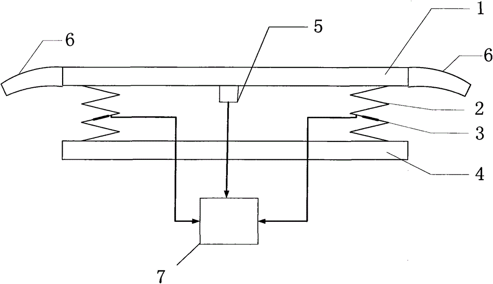
[0021] Such as figure 1 As shown, the fiber-optic pantograph jacking pressure online real-time detection system of this embodiment includes a pantograph carbon slide [1], an elastic plate [2], an optical fiber strain sensor [3], a carbon slide bracket [4], Fiber optic accelerometer [5], horn [6], and signal processing unit [7].

[0022] The optical fiber strain sensor [3] is used to measure the elastic strain of the elastic plate [2] to calculate the section force value F d .

[0023] The fiber optic accelerometer [5] is used to measure the inertial force F of the pantograph ine .

[0024] The pantograph carbon skateboard [1] and the carbon skateboard bracket [4] are supported and connected by the elastic plate [2], the optical fiber strain sensor [3] is pasted on the elastic plate [2], and the optical fiber accelerometer [7] is installed on the pantograph The lower surface of the carbon slide [1], the signal processing unit [5] is connected to the fiber optic strain senso...


PUM


Abstract

An optical fiber type on-line real-time pantograph lifting pressure detection system disclosed by the invention relates to the pantograph lifting pressure detection technology for railway locomotives, subway cars, electric multiple units or the like, and belongs to the field of safe train running monitoring. The optical fiber type on-line real-time pantograph lifting pressure detection system consists of a carbon pantograph slider, elastic plates, optical fiber strain sensors, a carbon slider support, an optical fiber accelerometer, cavels and a signal processing unit. The optical fiber strain sensors are used for measuring the elastic strain of the elastic plates, so that a sectional force value Fd can be worked out. The optical fiber accelerometer is used for measuring an inertial force value Fine applied on a pantograph. Lifting pressure Fc is worked out according a formula: Fc equal to Fd plus Fine. The optical fiber type on-line real-time pantograph lifting pressure detection system can utilize the optical fiber accelerometer and the optical fiber strain sensors to measure the lifting pressure of pantographs of railway locomotives, subway cars, electric multiple units or the like and adjust pantographs to move up or down according to the measured lifting pressure of pantographs in order to ensure that trains can obtain enough traction power and run safely and reliably, and also can provide data support for the analysis of pantograph-overhead contact system faults.

Description

technical field [0001] The invention relates to an online detection technology of pantograph jacking pressure based on the principle of optical fiber transmission, in particular to a pantograph jacking pressure detection technology used for railway locomotives, subway vehicles or EMUs, etc., and belongs to the field of train safety monitoring. Background technique [0002] The sensitive core of fiber optic strain sensor and fiber optic acceleration sensor is fiber grating, which utilizes the unique technical advantages of fiber grating: 1) Anti-electromagnetic interference, insulation, suitable for working in strong electromagnetic interference environment and high-voltage electric field environment; 2) Anti-environmental corrosion , Humidity resistance, suitable for use in field conditions; 3) Using wavelength division multiplexing technology, one optical fiber can connect multiple fiber grating sensors in series, light in weight, simple in wiring, smart in structure, suitab...

Claims


Application Information

Patent Timeline
Patent Type & Authority Patents(China)
IPC IPC(8): G01L1/24
Inventor 薛景锋陈刚张卫华高飞朴名鹏郭伟陈佳钰宋昊张毅翔
Owner BEIJING CHANGCHENG INST OF METROLOGY & MEASUREMENT AVIATION IND CORP OF CHINA
Why Eureka
Try Eureka