Arch wire shaper with compression bars at both ends

A technology of arch wire former and pressing rod, which is applied in medical science, dentistry, orthodontics and other directions, can solve the problems that the arch wire is easily separated from the groove, the finger surface is injured, and the operation is troublesome. The effect of avoiding finger injury and simplifying the forming process

Active Publication Date: 2016-04-27
杨娴睿 +3
View PDF6 Cites 0 Cited by
  • Summary
  • Abstract
  • Description
  • Claims
  • Application Information

AI Technical Summary

Problems solved by technology

[0004] 1. It needs to be molded in two steps. During this process, the arch wire is easy to break away from the groove, resulting in left-right asymmetry;
[0005] 2. When using it, you need to press the arch wire with your fingers. The operation is troublesome and difficult to control. After a long time, it is easy to damage the surface of your fingers.

Method used


Image

  • Arch wire shaper with compression bars at both ends
  • Arch wire shaper with compression bars at both ends
  • Arch wire shaper with compression bars at both ends

Examples


Embodiment Construction

[0022] The content of the present invention will be further described below in conjunction with the accompanying drawings, but it should not be understood that the protection scope of the present invention is limited thereto.

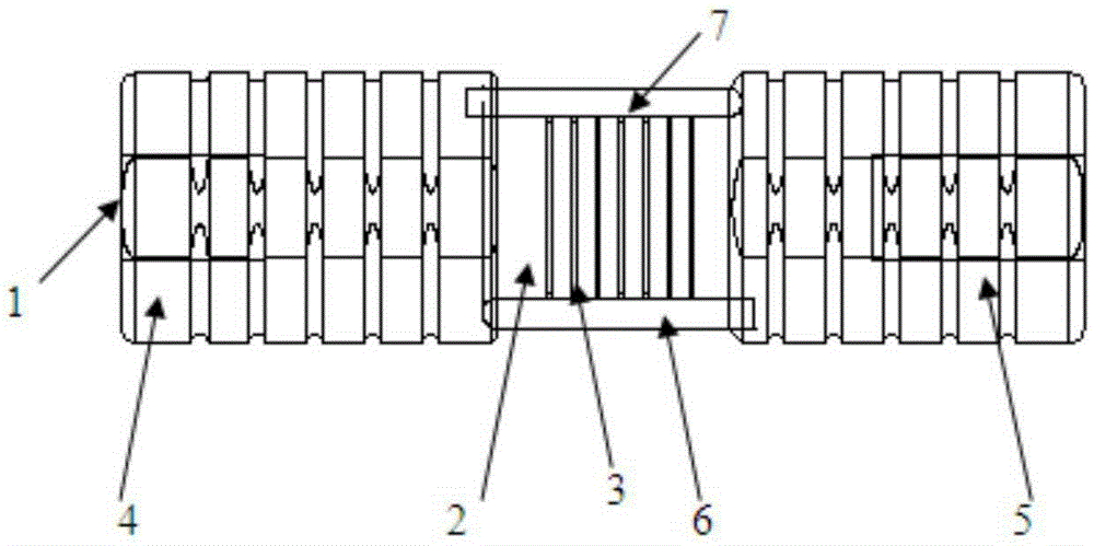
[0023] Such as figure 1 As shown, the arch wire shaper with compression rods at both ends includes a cylindrical shaped part 2 located in the middle of the shaft 1, and several grooves for placing arch wires are arranged on the outer surface of the shaped part 2 along the circumferential direction of its section. Slot 3. The width of the groove 3 is 0.016″, 0.017″, 0.018″, 0.019″, 0.022″ etc. (in imperial units), and the depth is 0.025″ (in imperial units), which match the size of the square archwire.

[0024] The two ends of the shaft 1 are provided with handles 4 and 5 respectively, and the two handles are sleeved on the shaft 1 and can be displaced along the shaft 1 and rotated around the shaft 1 . Wherein the inner side of the handle 4 is provided...


PUM


Abstract

The invention relates to a dentistry medical device, and provides an arch wire forming machine with pressure rods arranged at two ends. The forming machine comprises a cylindric molding part located in the middle part of a shaft. Grooves used for placing arc wires are arranged in the external surface of the molding part along the peripheral direction of the cross section. Handles are arranged at two sides of the shaft. A pressure rod is arranged at the inner side of one handle. The two handles are both sleeved on the shaft and can move along the shaft and rotate around the shaft. A pressure rod is also arranged at the inner side of the other handle. The two pressure rods are both parallel to the shaft, and the lower surfaces are cambered surfaces, and are tangent to the periphery of the external surface of the molding part. When the provided arch wire forming machine is compared to existing arch wire forming machines, the handles arranged at two ends of the arch wire forming machine are equipped with pressure rods. The handles can be rotated with two hands at the same time, and forming is finished after one-time operation. The symmetric form of a dental arch wire can be guaranteed, and the forming steps are simplified. The operation time of a doctor is saved, and the requirements of operation skills of a doctor are reduced. Injuries of fingers of a doctor are avoided and labour and time are saved.

Description

technical field [0001] The invention relates to a dental medical instrument, in particular to an arch wire shaper with compression rods at both ends. Background technique [0002] With the development of orthodontic medicine, the application of arch wire in orthodontic clinic is an essential and important part. In clinical orthodontics, the arch wire needs to be bent to a certain shape before correction, and a special arch wire shaper must be used for bending. At present, the structure of the arch wire shaper used clinically is: the whole is dumbbell-shaped, the cylindrical shape in the middle is connected to the handles at both ends through the shaft, and only one handle is provided with a pressure rod, and the clinician places the arch wire on it. The size matches the groove of the plastic part, and then press one end of the arch wire with the thumb of the left hand, and the pressing rod is driven to rotate on the surface of the plastic part by turning the handle, so that...

Claims


Application Information

Patent Timeline
Patent Type & Authority Patents(China)
IPC IPC(8): A61C7/02A61C7/00
Inventor 杨娴睿白丁韩向龙管国清
Owner 杨娴睿
Why Eureka
Try Eureka