
Thin-film demisting device

A defogging device and thin-film technology, which can be applied to clothing, helmets, helmet covers, etc., can solve problems such as visual impact, threats to the driver's personal safety, and driver's visual impact, and achieve the effect of avoiding water mist

Inactive Publication Date: 2014-01-22
周峰
View PDF5 Cites 2 Cited by
  • Summary
  • Abstract
  • Description
  • Claims
  • Application Information

AI Technical Summary

Problems solved by technology

However, in rainy weather, the mirror of the helmet will be covered with water droplets, and the accumulation of water droplets will affect the driver's vision, and in severe cases, it will threaten the driver's personal safety
[0003] A kind of water brushing helmet is specially designed. The core of the design is to set a large opening on the mirror surface of the helmet, and set two rotating shafts on both sides of the opening, and a wiper against the rotating shaft is provided beside each rotating shaft. A transparent film is wound between the two rotating shafts, and the rotating shaft separates the transparent film into two layers. The rotating shaft rotates under the action of an external force to drive the transparent film to rotate, and the rainwater falling on the transparent film will move with the film to the wiper for cleaning, so as to keep clear Sight, but when driving, there may be water mist on the film. Although the rain is scraped off, the water mist will also affect the line of sight, so how to drive the rotating shaft to scrape off the rain on the transparent film and eliminate the water mist is the current problem to be solved

Method used


Image

  • Thin-film demisting device
  • Thin-film demisting device
  • Thin-film demisting device

Examples


Embodiment

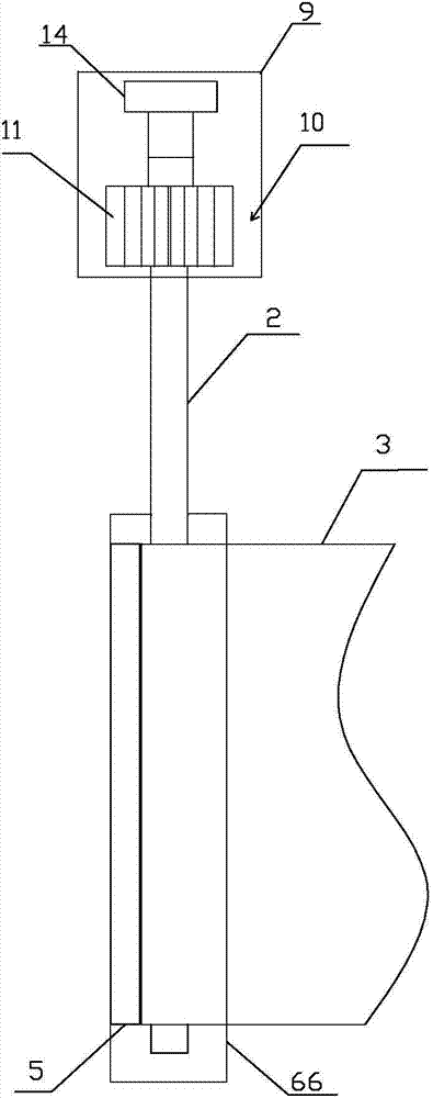
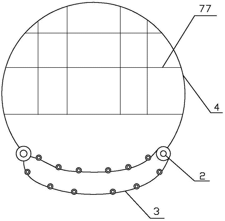
[0016] Embodiment: a kind of film defogging device for brushing water helmet, as Figure 1~3 As shown, it includes a storage battery (not shown) arranged in the helmet main body 4, a solar panel 77 arranged on the surface of the helmet main body 4, and rotating shafts 2 arranged on both sides of the opening of the helmet mirror (not shown). In the shaft box 66, a wiper 5 is fixed inside the shaft box 66, and a transparent film 3 is wound between the two shafts 2. The shaft 2 is a hollow rubber roller, and a heating wire 1 is arranged inside the shaft 2. A box body 9 is respectively provided above each rotating shaft 2, and a ventilation opening 10 that runs through the entire box body toward the forward direction is provided on the box body 9, and a rotating vane 11 that is arranged facing the ventilation opening is provided in the box body 9. , the rotating blade 11 is fixedly sleeved on the rotating shaft 2, the solar cell panel 77 is connected to the storage battery, and th...


PUM


Abstract

The invention discloses a thin-film demisting device. The thin-film demisting device comprises a storage battery arranged in a helmet body, a solar cell panel arranged on the surface of the helmet body and rotary shafts arranged on two sides of an opening of the helmet mirror face, wherein a transparent thin film is wound between the rotary shafts, the rotary shafts are hollow rubber rollers, heating wires are arranged in the rotary shafts, one box body is respectively arranged above the rotary shafts and provided with a ventilation opening penetrating the whole box body towards the advancing direction, rotating blades facing the ventilation openings are arranged in the box bodies and fixedly connected onto the rotary shafts in a sleeved mode, the solar cell panel is connected with the storage battery, and the storage battery is connected with the heating wires. In the clear weather, the solar cell panel on the helmet can be utilized to charge the storage battery. When the thin-film demisting device is used in the rainy weather, the device is switched on to enable the storage battery to perform power supply and heating on the heating wires in the rotary shafts, heat of the heating wires is transferred to the rotary shafts, accordingly moisture on the transparent thin film can be effectively evaporated, and water mist is avoided.

Description

technical field [0001] The invention relates to a water brushing helmet used by a driver, in particular to a film defogging device for a water brushing helmet. Background technique [0002] When driving a motorcycle or electric bicycle, according to traffic regulations, in order to ensure driving safety, the driver must wear a helmet. However, when encountering rainy weather, the mirror surface of the helmet will be covered with water droplets, and the accumulation of water droplets will affect the driver's vision and seriously threaten the driver's personal safety. [0003] A kind of water brushing helmet is specially designed. The core of the design is to set a large opening on the mirror surface of the helmet, and set two rotating shafts on both sides of the opening, and a wiper against the rotating shaft is provided beside each rotating shaft. A transparent film is wound between the two rotating shafts, and the rotating shaft separates the transparent film into two laye...

Claims


Application Information

Patent Timeline
Patent Type & Authority Applications(China)
IPC IPC(8): A42B3/24A42B3/26
Inventor 周峰
Owner 周峰
Learn More