Fuze body object simulation method and system

A target simulation and fuze technology, applied in radio wave measurement systems, instruments, etc., can solve the problem that point target simulators cannot fuse target simulation, and achieve the effect of improving simulation degree and accuracy

Inactive Publication Date: 2014-01-15
北京华清瑞达科技有限公司
View PDF4 Cites 17 Cited by
  • Summary
  • Abstract
  • Description
  • Claims
  • Application Information

AI Technical Summary

Problems solved by technology

[0003] Aiming at the defects in the prior art, the present invention solves the problem that the point target simulator cannot perform real simulation on the fuze target

Method used


Image

  • Fuze body object simulation method and system
  • Fuze body object simulation method and system
  • Fuze body object simulation method and system

Examples


Embodiment 1

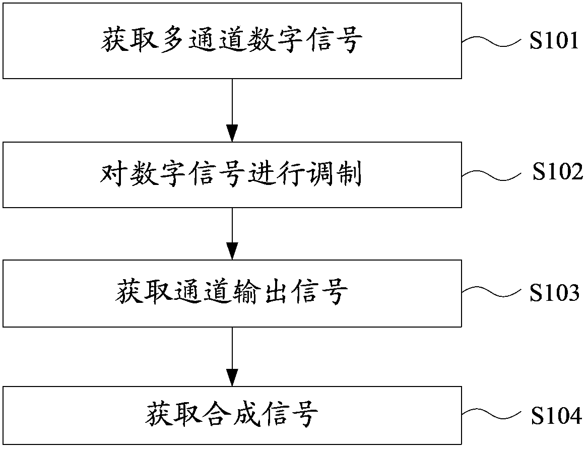
[0020] figure 1 It is a schematic flow chart of a method for simulating a fuze body target in the present invention. like figure 1 As shown, the method mainly includes the following steps:

[0021] S101: Acquire multi-channel digital signals;

[0022] In the above steps: sampling the radar transmission signal to obtain a digital signal, and distributing the digital signal to multiple digital signal channels; and specifically including: receiving the radar signal through the receiving antenna; performing down-conversion processing according to the radar signal , to obtain a low-intermediate frequency radar signal; sampling the low-intermediate frequency radar signal to obtain a digital signal, the specific radar signal can be sent to the down-conversion link unit through the receiving antenna, and the down-conversion link unit can further complete the amplification of the radio frequency signal. And in the above steps, the number of digital signal channels can be determined ...

Embodiment 2

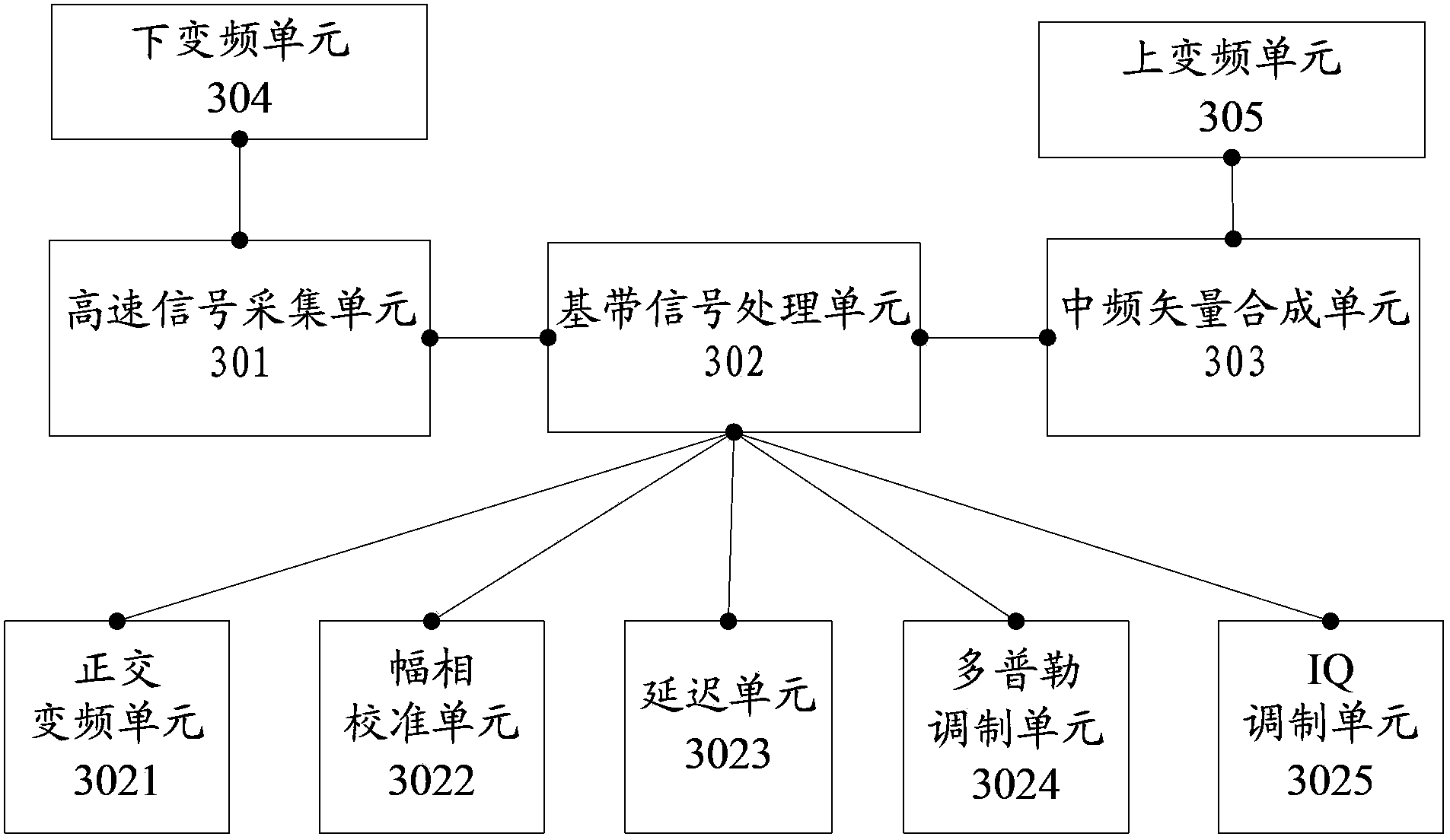
[0030] image 3 It is a schematic diagram of the composition of a fuze object simulation system of the present invention. like image 3 As shown, it includes: a high-speed signal acquisition unit 301, a baseband signal processing unit 302, an intermediate frequency vector synthesis unit 303, wherein,

[0031]The high-speed signal acquisition unit 301 is configured to sample radar transmission signals to obtain digital signals; distribute the digital signals to multiple digital signal channels;

[0032] The baseband signal processing unit 302 is used for modulating the digital signal of the digital signal channel in each digital channel according to the scatter point speed and delay amount of each digital signal channel; and performing digital / analog conversion on the modulated digital signal Obtain an output signal of the digital signal channel;

[0033] The intermediate frequency vector synthesis unit 303 is configured to unify the phases of the output signals of the plura...


PUM


Abstract

The invention discloses a fuze body object simulation method. The method specifically comprises: performing sampling on radar emission signals, obtaining digital signals, and distributing the digital signals to a plurality of digital signal channels; in each digital signal channel, according to the speed of the scattering points and the delay amount of each digital signal channel, modulating the digital signals of the digital signal channels; performing digit-simulation conversion on the modulated digital signals for obtaining the output signals of the digital signal channels; and unifying the phases of the output signals of the plurality of the digital channels, synthesizing the output signal obtaining synthesis signals of the digital channels at an intermediate frequency vector, and according to the synthesis signals, obtaining high-frequency synthesis signals and performing space radio frequency radiation. By the method and system, the problem can be solved that a point target simulator cannot perform real simulation on a fuze object, the fuze body object can be simulated in a more real manner, the phase continuity can be maintained when the signals are delayed, the actual effects of fuze simulation are achieved, and the simulation degree and precision of a radar simulation system are improved.

Description

technical field [0001] The invention relates to the field of radar radio frequency simulation and is applied to a radar simulation system, in particular to a fuze body target simulation method and system. Background technique [0002] Radar signal simulator is the combination of simulation technology and radar technology. It evaluates the technical and tactical indicators of the tested radar by simulating the radar echo signal, and assists in testing the power and accuracy of the radar. There have been a lot of reports on research in this field abroad: KOR Electronics of the United States has developed a digital radar environment simulator (Digital Radar Environment Simulator), and HP has produced an X-band radar moving target based on a parallel FASS (Frequency Agile Signal Simulator). Signal Simulator. Domestic research reports on radar signal simulators have appeared successively since the 1990s: Beihang University and the 601 Institute of the Ministry of Aerospace Scie...

Claims


Application Information

Patent Timeline
Patent Type & Authority Applications(China)
IPC IPC(8): G01S7/282
CPCG01S7/4052
Inventor 宋兵兵孙亚光梁志恒朱骏潘明海
Owner 北京华清瑞达科技有限公司
Why Eureka
Try Eureka