
Method and special check valve for preventing contraflow of oil circuit of transformer

A technology of reverse flow and transformer oil, applied in the field of transformers, can solve problems such as unfavorable transformer heat dissipation, reverse flow of transformer oil, short circuit of oil circuit, etc., to completely prevent reverse oil flow, increase oil flow speed, circulation and cut-off reliable effect

Inactive Publication Date: 2014-01-15
BAODING BAOLING TRANSFORMER
View PDF6 Cites 7 Cited by
  • Summary
  • Abstract
  • Description
  • Claims
  • Application Information

AI Technical Summary

Problems solved by technology

[0002] The transformer oil pump is the power source for forced oil circulation cooling of large oil-immersed transformers. When the transformer oil pump is in standby, because there is no special check valve, the reverse flow of transformer oil may occur, which will lead to a short circuit in the oil circuit, which is not conducive to the heat dissipation of the transformer.

Method used


Image

  • Method and special check valve for preventing contraflow of oil circuit of transformer
  • Method and special check valve for preventing contraflow of oil circuit of transformer
  • Method and special check valve for preventing contraflow of oil circuit of transformer

Examples


Embodiment 1

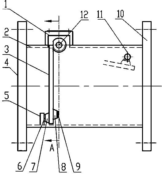
[0034] Embodiment one, with reference to the attached Figure 9 , when in use, the axes of flange one, valve box and flange two are placed at an inclination of 35° from the vertical line, and when installed, the transformer radiator manifold is located on the upper left of flange one. The flow direction of the transformer oil is downward. Under normal conditions, the baffle is naturally drooped by gravity, and the baffle stops at the second position of the limit plate, and the forward transformer oil flow passes smoothly; when the reverse transformer oil flow occurs, it is affected by the transformer When the oil flows, the baffle is impacted and returns to the position of the limit plate 2. At this time, the baffle is perpendicular to the axis of the valve box and the flange 2. The valve box is closed and cut off, and the transformer oil circuit is cut off, thereby inhibiting reverse flow. of transformer oil flow.

Embodiment 2

[0035] Embodiment two, referring to the attached Figure 10 , when in use, the axes of flange 1, valve box and flange 2 are placed at an angle of 35° to the vertical line, and when installed, the transformer radiator manifold is located at the upper right of flange 1.


PUM


Abstract

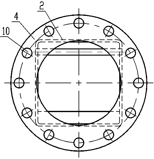
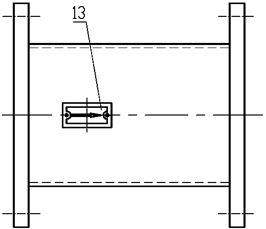
The invention relates to a method and special check valve for preventing contraflow of an oil circuit of a transformer and belongs to the technical field of transformers. According to the technical scheme, a supporting plate is welded on the upper wall of a valve box, the supporting plate is of a shaft sleeve structure, a rotary shaft is arranged in the shaft sleeve, and a baffle is fixed on the rotary shaft; the upper end of the baffle is fixed on the rotary shaft, a first limiting base and a second limiting base are arranged on the two sides of the lower end of the baffle respectively, a first limiting plate is arranged on the lower wall of the interior of the valve box and is matched with the first limiting base, and a second limiting plate is arranged on the upper wall of the interior of the valve box and is matched with the second limiting base. The method and special check valve for preventing contraflow of the oil circuit of the transformer have the advantages that the structure is simple, installation is convenient, feasibility is strong, and the oil flow can be unblocked and cut off reliably. According to the method and special check valve for preventing contraflow of the oil circuit of the transformer, by means of the gravity principle, the check valve is superior to an electric check valve or a spring type check valve, and the problem that the oil flow of the check valve is blocked due to a power failure or spring failure is solved; due to the fact that the rotary shaft is located at the position of the protruding supporting plate, the influence on the forward oil flow is reduced, and the reverse oil flow is blocked more quickly and completely.

Description

technical field [0001] The invention relates to a method for preventing reverse flow in a transformer oil circuit and a special check valve, belonging to the technical field of transformers. Background technique [0002] The transformer oil pump is the power source for forced oil circulation cooling of large oil-immersed transformers. When the transformer oil pump is in standby, because there is no special check valve, the reverse flow of transformer oil may occur, which will lead to a short circuit in the oil circuit, which is not conducive to the heat dissipation of the transformer. Contents of the invention [0003] The purpose of the present invention is to provide a method for preventing reverse flow in the transformer oil circuit and a special check valve, which increases the oil flow speed, improves the reaction accuracy, and can prevent the reverse oil flow more thoroughly. The structure is simple and the installation is convenient. It has good manufacturability, c...

Claims


Application Information

Patent Timeline
Patent Type & Authority Applications(China)
IPC IPC(8): F16K15/03F16K27/02F16K37/00H01F27/14
CPCF16K15/03F16K27/0227F16K37/0008H01F27/12
Inventor 郑泉王维征郭飞李习芹王亚静王友双
Owner BAODING BAOLING TRANSFORMER
Learn More