
Method used for reciprocating impact excavation by arranging discharge port for discharging, and reciprocating impact excavator used for implementing method by arranging discharge pot for discharging

An excavator and material hole technology, which is applied in the field of machinery, can solve the problems of inability to discharge and the inability of continuous production of multi-layer impact head excavators.

Active Publication Date: 2014-01-15
刘素华
View PDF4 Cites 0 Cited by
  • Summary
  • Abstract
  • Description
  • Claims
  • Application Information

AI Technical Summary

Problems solved by technology

In order to solve the problem of extruding material between the impact heads, the present invention sets a discharge hole on the impact and blanking mechanism, and makes the shape and / or arrangement of the material teeth of the outer layer of the punching material beneficial to the material teeth of the inner layer of the punching material. The structure of the material outflow, the invention of this structure greatly reduces the extrusion damage to the material block, reduces the resistance of the punching teeth, and solves the problem that the material sandwiched between the two impact heads cannot be discharged when the previous multi-layer impact heads are excavated. Multi-layer impact head excavator cannot continuously produce obstacles, improving the service life of the equipment

Method used


Image

  • Method used for reciprocating impact excavation by arranging discharge port for discharging, and reciprocating impact excavator used for implementing method by arranging discharge pot for discharging
  • Method used for reciprocating impact excavation by arranging discharge port for discharging, and reciprocating impact excavator used for implementing method by arranging discharge pot for discharging
  • Method used for reciprocating impact excavation by arranging discharge port for discharging, and reciprocating impact excavator used for implementing method by arranging discharge pot for discharging

Examples


Embodiment 1

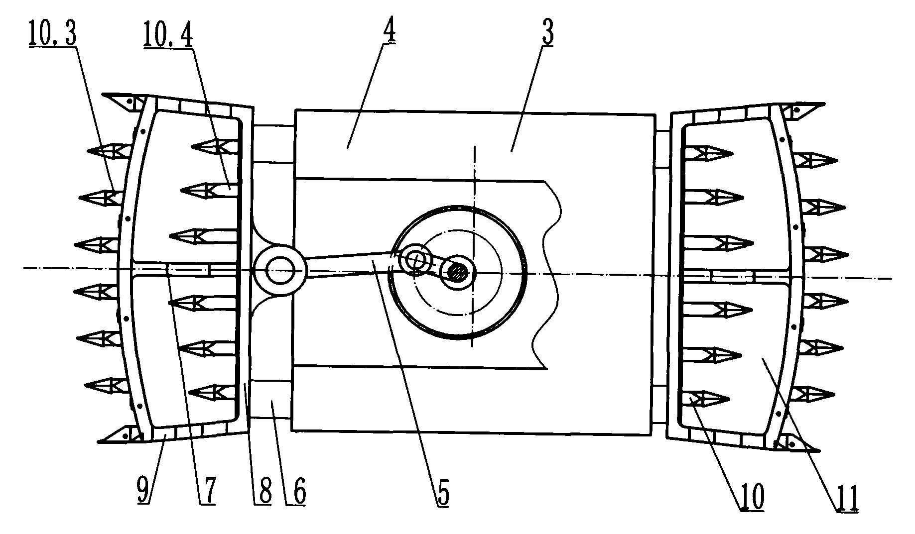
[0098] Such as Figure 1 to Figure 8 As shown, a reciprocating impact mining machine is provided with a discharge hole, including a body 1, a traveling mechanism 2, etc., and an impact blanking mechanism 3, etc. The impact blanking mechanism 3 includes an impact power box 4 and a power impact piece 5 , impact guide 6, impact head 7, etc., the impact head 7 is composed of a support seat 8, punching teeth 10, etc., the support seat 8 includes a discharge hole frame 9, etc., and the discharge hole frame 9 includes one or more discharge holes 11. The support seat 8 is equally connected with the discharge hole frame 9 or integrated. The punching teeth 10 are set on the discharge hole frame 9 or the punching teeth are arranged on the discharge hole frame 9 and the support seat 8. The punching teeth 10 Including punching the outer layer material tooth 10.1, punching the inner layer material tooth 10.2, etc., the shape and / or arrangement of the punching outer layer material tooth 10.1...

Embodiment 2

[0118] Such as Figure 9 to Figure 10 As shown, the discharge hole 11 is a trapezoidal discharge hole, and may also be an arc-shaped discharge hole, a square discharge hole, an arched discharge hole, a triangular discharge hole, or a special-shaped discharge hole.

[0119] Both ends of the impact guide 6 are asymmetrically provided with supporting seats 8, and the impact guide 6 and the supporting seats 8 are equally connected or integrated.

[0120] An anti-damage impact driver structure 20 and the like are provided between the power impact member 5 and the support base 8 or on the power impact member 5 , and the power impact member 5 and the support base 8 are connected equally or separately or integrally.

[0121] The anti-damage impact driver structure 20 includes a rotating anti-damage impact driver structure 20.1, etc., the power impact member 5 drives the punching tooth 10 to impact, the impact reaction force is applied to the anti-damage impact driver structure 20, etc...

Embodiment 3

[0129] Such as Figure 11 to Figure 16 As shown, a reciprocating impact mining machine is provided with a discharge hole, including a body 1, a traveling mechanism 2, etc., and an impact blanking mechanism 3, etc. The impact blanking mechanism 3 includes an impact power box 4 and a power impact piece 5 , impact guide 6, impact head 7, etc., the impact head 7 is composed of a support seat 8, punching teeth 10, etc., the support seat 8 includes a discharge hole frame 9, etc., and the discharge hole frame 9 includes one or more discharge holes 11. The support seat 8 is equally connected with the discharge hole frame 9 or integrated. The punching teeth 10 are set on the discharge hole frame 9 or the punching teeth are arranged on the discharge hole frame 9 and the support seat 8. The punching teeth 10 Including punching the outer layer material tooth 10.1, punching the inner layer material tooth 10.2, etc., the shape and / or arrangement of the punching outer layer material tooth 10...


PUM


Abstract

The invention discloses a method used for reciprocating impact excavation by arranging a discharge port for discharging, and a reciprocating impact excavator used for implementing the method by arranging the discharge pot for discharging. The reciprocating impact excavator comprises an impact blanking mechanism. The impact blanking mechanism comprises an impact power box, a powered impact component, an impact guiding element, and an impact head; the impact head is composed of a supporting seat, a discharge port frame, and impact teeth, or is composed of the supporting seat and the impact teeth; the discharge port frame is arranged on the supporting seat; the discharge port frame comprises one or more discharge ports; the discharge port is advantageous for discharging material punched out by teeth for impacting the inner material layer; the impact blanking mechanism is arranged on a machine body, a travelling mechanism is arranged on the machine body; the impact head is driven by the powered impact component to complete reciprocating motion, the discharge port is used for discharging materials; so that the machine body is capable of moving smoothly; continuous excavation is realized; a problem that continuous excavation can not be realized because materials clamped between the impact teeth can not be discharged is solved; material collection, material discharge and material charging of the excavator provided with the impact head are realized smoothly; and excavation efficiency is increased.

Description

technical field [0001] The invention belongs to the field of machinery, and is especially suitable for the mining field, and in particular relates to a reciprocating impact excavation method with a discharge hole and a reciprocating impact mining machine for implementing the method. Background technique [0002] The impact heads of impact mining machines such as existing punching mining equipment are generally single-layer or multi-layer impact heads. The inner impact head and the outer impact head of the multi-layer impact head are mostly arranged close to each other. When the punching teeth of the inner impact head are set in one row and the punching teeth are rare, the impact resistance of the punching teeth will increase a lot if the excavation width is slightly wider. The material punched by the over-dense inner layer punching teeth cannot pass through, that is, the inner impact head close to the material layer sandwiches the material between the inner and outer impact...

Claims


Application Information

Patent Timeline
IPC IPC(8): E21C27/00E21C27/46
CPCE21C27/02
Inventor 刘素华
Owner 刘素华
Learn More