
Electric rail clamping device of throw-off carriage

A technology of rail clamps and unloading vehicles, which is applied in the direction of conveyor objects, transportation and packaging, etc., which can solve the problems of poor operation reliability, complicated structure, and danger, and achieve high safety and reliability, simple structure, and high applicability. Effect

Inactive Publication Date: 2014-01-15
ANHUI YONGSHENG MACHINERY
View PDF7 Cites 3 Cited by
  • Summary
  • Abstract
  • Description
  • Claims
  • Application Information

AI Technical Summary

Problems solved by technology

Because the component force in the running direction generated during the material lifting process is to make the unloading vehicle slide in the running direction, in order to ensure its reliable positioning and complete the unloading work under heavy load conditions, the general unloading vehicle is equipped with a brake. In practical applications, it often occurs that the wheels do not roll but slide on the track after braking, which seriously affects the normal operation of the equipment and may endanger the safety of people and equipment
[0003] Therefore, it is necessary to add a rail clamp on the unloading truck. Although there is a manual type of rail clamp in industrial applications, it cannot meet the requirements of automatic control of the system, and it is very inconvenient to operate on a running unloading truck. and there is a certain risk
However, ordinary electric or hydraulic rail clamps have the defects of complex structure, poor operation reliability, and can not be well adapted to the actual supporting needs of unloading trucks.

Method used


Image

  • Electric rail clamping device of throw-off carriage
  • Electric rail clamping device of throw-off carriage
  • Electric rail clamping device of throw-off carriage

Examples


Embodiment 1

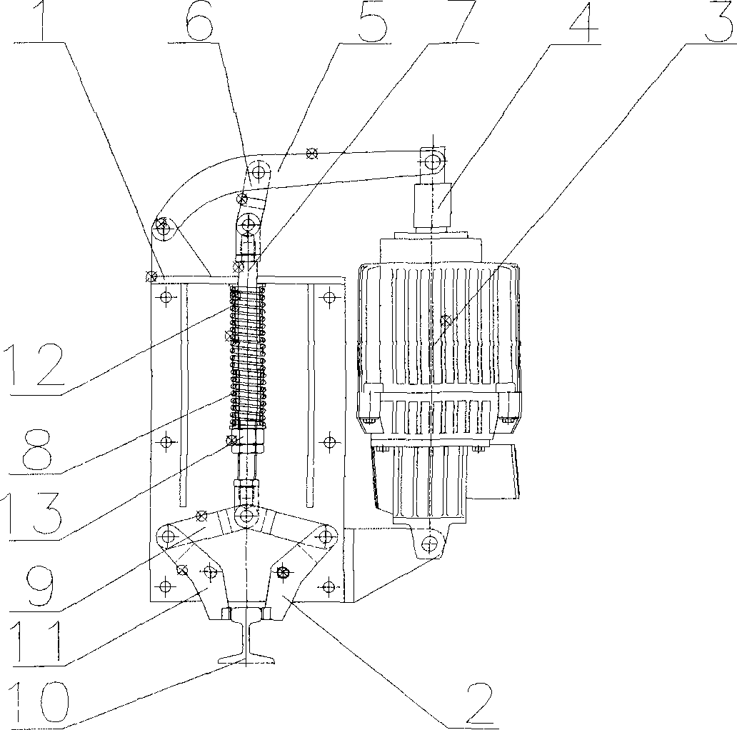
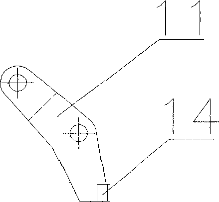
[0018] see figure 1 , an electric rail clamp for an unloading vehicle provided by the present invention includes a rail clamp bracket 1 arranged on one side of the unloading vehicle, and a rail clamp 2 connected by power and an electric rail clamp are installed on the rail clamp bracket 1 . Hydraulic push rod pusher 3, a large connecting rod 5 is hinged between the top of the rail clamp bracket 1 and the push rod 4 on the top of the electrohydraulic push rod pusher 3, and an upper connecting rod is hinged below the large connecting rod 5 in turn 6 and the main strut 7, the outer wall of the main strut 7 is covered with a spring 8, the rail clamp 2 includes two sets of lower links 9 hinged at the bottom of the main strut 7 at the same time, the two sets of lower links 9 two groups of clamping blocks 11 for clamping the track 10 are hinged symmetrically at the bottom.

Embodiment 2

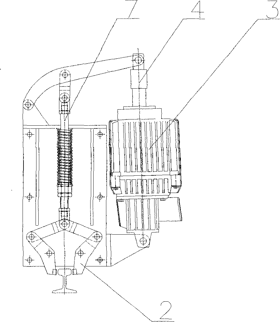
[0020] The working process of the present invention is: when the electrohydraulic push rod pusher 1 is energized, its push rod 4 is pushed out, and the thrust is transmitted to the main strut 7 through the connecting rod mechanism, so that the main strut 7 moves upward, and the rail clamp 2 Complete the release action (such as figure 2 On the contrary, when the push rod 4 is retracted, the main strut 7 pushes the lower link 9 under the pre-compression force of the spring 8, so that the lower end of the clamping block 11 clamps the track 10.

Embodiment 3

[0022] As a further improvement to Embodiment 1, a guide sleeve 12 is provided between the spring 8 and the main strut 7 to prevent the spring 8 from being deformed after being compressed.


PUM


Abstract

The invention discloses an electric rail clamping device of a throw-off carriage. The electric rail clamping device comprises a rail clamping device support arranged on one side of the throw-off carriage, wherein rail clamping tongs and an electric hydraulic pushing rod pushing device which are in power connection are installed on the rail clamping device support, a large connecting rod is hinged between the top of the rail clamping device support and a pushing rod on the top of the electric hydraulic pushing rod pushing device, an upper connecting rod and a main supporting rod are sequentially hinged below the large connecting rod, and the outer wall of the main supporting rod is sleeved with a spring. The rail clamping tongs comprise two sets of lower connecting rods which are hinged to the bottom end of the main supporting rod at the same time, and two sets of clamping blocks which are used for clamping a rail are symmetrically hinged to the bottom ends of the two sets of lower connecting rods. According to the electric rail clamping device, the electric hydraulic pushing rod pushing device is utilized as a power source, on the basis of the lever principle, the lifting force is transmitted to the rail clamping tongs, clamping of the rail is achieved, the safety and reliability are high, in addition, due to the fact that the rail clamping tongs are only provided with one positioning shaft, the position of the positioning shaft can be floated according to the position of the rail, on the premise that the straightness error of the rail is large, the clamping action can be reliably completed, and the applicability is high.

Description

technical field [0001] The invention relates to a rail clamp, in particular to an electric rail clamp for an unloading vehicle. Background technique [0002] The belt conveyor unloading vehicle is a device that can continuously unload materials at any point. Because the component force in the running direction generated during the material lifting process is to make the unloading truck slide in the running direction, in order to ensure its reliable positioning and complete the unloading work under heavy load conditions, the general unloading truck is equipped with brakes. In practical applications, it often occurs that the wheels do not roll but slide on the track after braking, which seriously affects the normal operation of the equipment and may endanger the safety of people and equipment. [0003] Therefore, it is necessary to add a rail clamp on the unloading car. Although there is a manual type of rail clamp in industrial applications, it cannot meet the requirements o...

Claims


Application Information

Patent Timeline
Patent Type & Authority Applications(China)
IPC IPC(8): B65G47/34B65G47/74
Inventor 徐春杰许志
Owner ANHUI YONGSHENG MACHINERY
Learn More