Novel cantilever drilling machine lifting mechanism

The technology of a cantilever drilling machine and a lifting mechanism is applied in the field of machine tools, which can solve the problems of weak resistance to the eccentric moment of the cantilever, wear or breakage of a single lead screw, and passiveness, and achieve the effect of good use effect.

Inactive Publication Date: 2014-01-15
XUZHOU CONTENT TRANSMISSION TECH
View PDF0 Cites 0 Cited by
  • Summary
  • Abstract
  • Description
  • Claims
  • Application Information

AI Technical Summary

Problems solved by technology

[0002] At present, the cantilever of the cantilever drilling machine is mostly a vertical lifting mechanism on the single screw of the column, and the motor drives the single screw on the column to rotate through the gearbox to drive the cantilever of the drilling machine to rise or fall; at present, the cantilever drilling machine The cantilever is mostly a cantilever beam structure. The cantilever will generate a certain eccentric moment on the column of the drilling machine and load it on the single screw on the column. If so, the single screw on the column can resist the eccentric moment of the cantilever. The ability is weak, so it is easy to cause the problem of wear or break of the single lead screw on the column, so that it is easy to cause passive work.

Method used


Image

  • Novel cantilever drilling machine lifting mechanism

Examples


Embodiment Construction

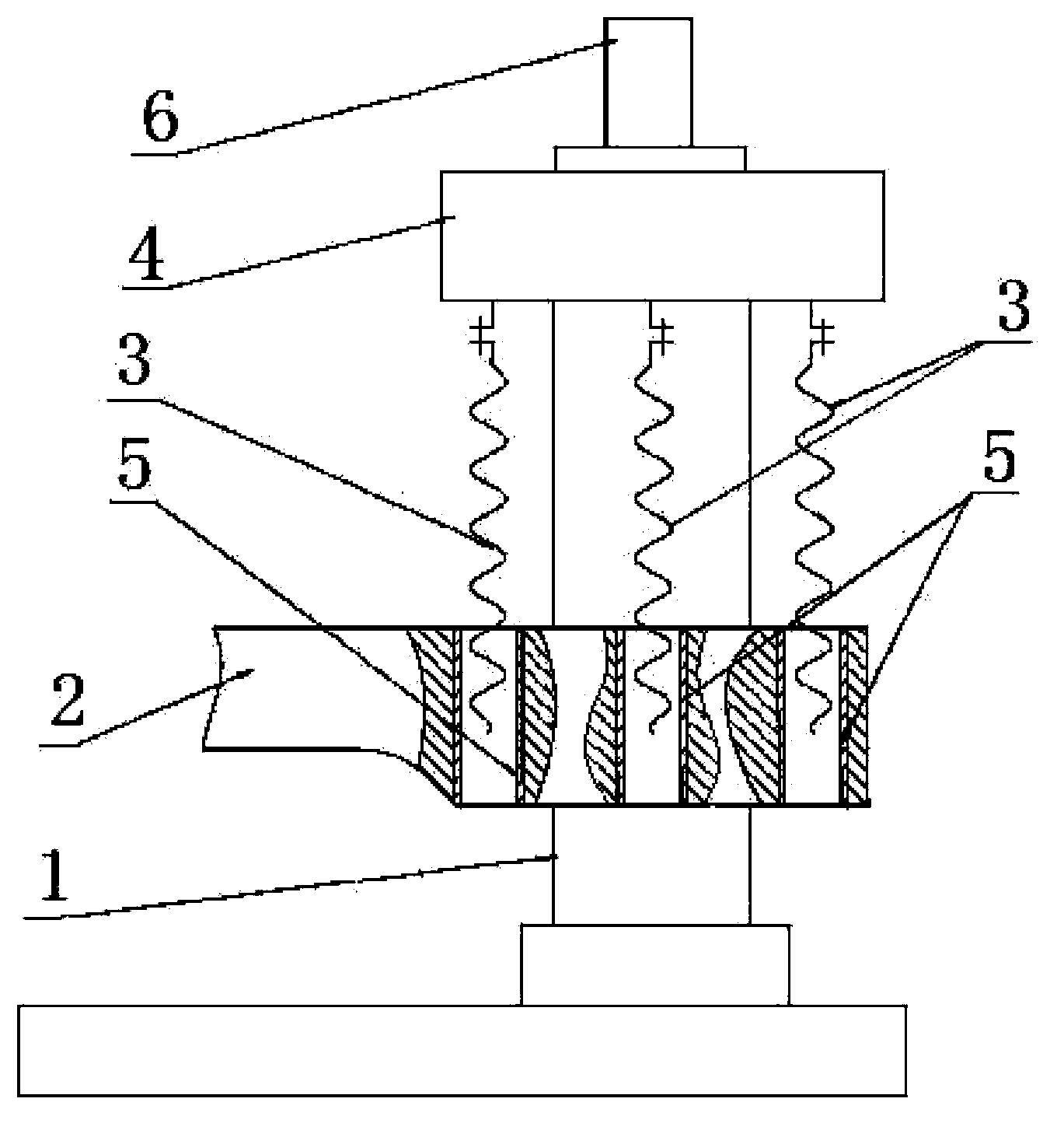
[0009] figure 1 Among them, it is composed of: column (1), cantilever (2), screw (3), reduction box (4), screw nut (5) and motor (6); it is on the column (1) of the drilling machine Three lead screws (3) coaxial with the column (1) are arranged respectively, so that the structure of the three lead screws (3) has a strong effect of resisting the eccentric moment of the cantilever (2). Therefore, the lead screw (3) Not easy to be frayed or broken.


PUM


Abstract

The invention discloses a novel cantilever drilling machine lifting mechanism. The novel cantilever drilling machine lifting mechanism is characterized in that three screw rods sharing the same axis with a stand column are arranged on the stand column of cantilever drilling machine respectively, and the three screw rods of the stand column can strongly resist eccentric torque of a cantilever, and therefore the screw rods are not prone to abrasion or fracture.

Description

technical field [0001] The invention relates to a lifting mechanism of a cantilever drilling machine, in particular to a novel lifting mechanism of a cantilever drilling machine, which belongs to the technical field of machine tools. Background technique [0002] At present, the cantilever of the cantilever drilling machine is mostly a vertical lifting mechanism on the single screw of the column, and the motor drives the single screw on the column to rotate through the gearbox to drive the cantilever of the drilling machine to rise or fall; at present, the cantilever drilling machine The cantilever is mostly a cantilever beam structure. The cantilever will generate a certain eccentric moment on the column of the drilling machine and load it on the single screw on the column. If so, the single screw on the column can resist the eccentric moment of the cantilever. Ability is weak, therefore, easily causes the wearing and tearing of single lead screw on its column or the proble...

Claims


Application Information

Patent Timeline
Patent Type & Authority Applications(China)
IPC IPC(8): B23B47/00B23Q1/46
CPCB23Q1/46
Inventor 藏继民
Owner XUZHOU CONTENT TRANSMISSION TECH
Why Eureka
Try Eureka