Non-wear induction speed reducing and changing machine

A variable speed, wear-free technology, applied in the field of speed reducers, can solve the problems of reducing the service life of the speed reducers, reducing the working efficiency of the speed reducers, and wasting equipment power.

Inactive Publication Date: 2014-01-08
梁慎清
View PDF5 Cites 0 Cited by
  • Summary
  • Abstract
  • Description
  • Claims
  • Application Information

AI Technical Summary

Problems solved by technology

The deceleration and shifting of the above-mentioned traditional deceleration and transmission are mainly realized through gear transmission. The problems existing through gear transmission are: because the gear transmission will produce frictional resistance and mechanical wear, on the one hand the mechanical wear will reduce the service life of the deceleration and transmission. On the other hand, the frictional resistance will also reduce the working efficiency of the transformer, and overcoming the frictional resistance will waste the electric energy of the equipment

Method used


Image

  • Non-wear induction speed reducing and changing machine

Examples


Embodiment Construction

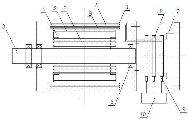
[0008] see figure 1 , the wear-free induction deceleration machine of the present invention comprises a low-speed rotating body and a high-speed rotating body placed in the low-speed rotating body, the low-speed rotating body has a cylindrical shell 1, and the inner wall of the cylindrical shell 1 is connected with a low-speed rotating body iron Core 2, low-speed rotating body core 2 is evenly distributed with low-speed rotating body induction coil A and low-speed rotating body induction coil B from outside to inside, the high-speed rotating body includes high-speed rotating body shaft 3 and connected with high-speed rotating body shaft 3 The high-speed rotating body iron core 4, the high-speed rotating body iron core 4 is evenly distributed with the high-speed rotating body induction coil 5, the high-speed rotating body 3 of the high-speed rotating body passes through the bearing 6 and the cylindrical shell 1 of the low-speed rotating body Connected, there is a gap between th...


PUM


Abstract

The invention discloses a non-wear induction speed reducing and changing machine which comprises a low-speed rotating body and a high-speed rotating body arranged in the low-speed rotating body. The low-speed rotating body is provided with a cylindrical shell; the inner wall of the cylindrical shell is connected with a low-speed rotating body iron core; a low-speed rotating body induction coil A and a low-speed rotating body induction coil B are uniformly distributed on the low-speed rotating body iron core from outside to inside; the high-speed rotating body comprises a high-speed rotating body shaft and a high-speed rotating body iron core; a high-speed rotating body induction coil is uniformly distributed on the high-speed rotating body iron core; the high-speed rotating body can rotate in the low-speed rotating body; the cylindrical shell is connected with a cylindrical sliding ring mounting body; a speed reduction sliding ring is arranged on the cylindrical sliding ring mounting body; the low-speed rotating body induction coil A is connected with the current input end of the speed reduction sliding ring by a wire; and the current output end of the speed reduction sliding ring is connected with an electricity load by an electric brush. According to the invention, due to no friction resistance and mechanical wear which are generated by transmission of a mechanical gear, service life of the non-wear induction speed reducing and changing machine is prolonged and meanwhile, the aim of saving energy is fulfilled.

Description

technical field [0001] The invention relates to a speed reduction machine, in particular to a wear-free induction speed reduction machine. Background technique [0002] The working principle of the traditional deceleration and transmission machine is mainly to use gear transmission at all levels to achieve the purpose of deceleration and transmission. For example, a small gear can be used to drive a large gear to achieve a certain deceleration purpose, and then the multi-stage structure can be used to greatly reduce the speed. up. The deceleration and shifting of the above-mentioned traditional deceleration and transmission are mainly realized through gear transmission. The problems existing through gear transmission are: because the gear transmission will produce frictional resistance and mechanical wear, on the one hand the mechanical wear will reduce the service life of the deceleration and transmission. On the other hand, the frictional resistance will also reduce the w...

Claims


Application Information

Patent Timeline
IPC IPC(8): H02K53/00
Inventor 梁慎清
Owner 梁慎清
Why Eureka
Try Eureka