
High-speed angular contact ball bearing damage fault dynamic analysis method

An angular contact ball bearing, dynamic technology, applied in special data processing applications, instruments, electrical digital data processing, etc., can solve the change of the line of action, cannot accurately simulate the instantaneous motion characteristics of bearing components, and does not comprehensively consider the complex dynamics of three-dimensional motion problems, such as learning phenomena, to achieve the effect of accurate analysis

Active Publication Date: 2014-01-08
XI AN JIAOTONG UNIV
View PDF2 Cites 23 Cited by
  • Summary
  • Abstract
  • Description
  • Claims
  • Application Information

AI Technical Summary

Problems solved by technology

[0004] From the above searches, it is found that the bearing dynamic models used in the existing literature are not perfect, and do not comprehensively consider the three-dimensional motion of each bearing element and the complex dynamic phenomena exhibited by high-speed angular contact ball bearings such as relative sliding and lubricated traction. Impossible to accurately simulate the instantaneous motion characteristics of each bearing element after a fault occurs
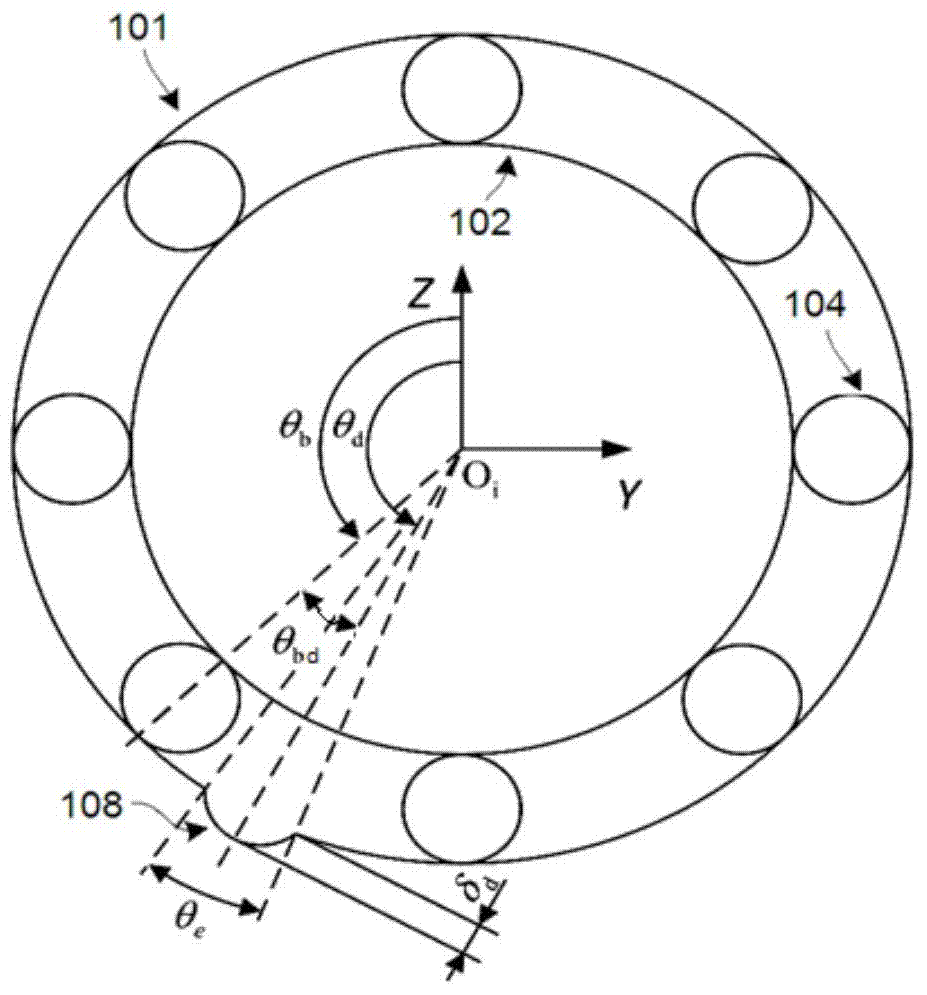
In addition, due to the occurrence of faults, the contact characteristics between the rolling ball and the raceway will change, which is mainly manifested in: the fault will cause the approach amount between the rolling ball and the raceway to increase above the original elastic contact position. The additional displacement introduced by the material; the appearance of the fault will cause the geometric characteristics of the damaged area to change, which will lead to the change of the Hertzian contact relationship; in the damaged area, the line of action of the ball / raceway contact load will change
However, none of the current research has fully considered the above issues

Method used


Image

  • High-speed angular contact ball bearing damage fault dynamic analysis method
  • High-speed angular contact ball bearing damage fault dynamic analysis method
  • High-speed angular contact ball bearing damage fault dynamic analysis method

Examples


Embodiment Construction

[0035] see figure 1 , the dynamic method of high-speed angular contact ball bearing damage fault of the present invention comprises: consider three-dimensional motion, relative sliding, lubricated traction, establish the dynamic model of high-speed angular contact ball bearing; Establish a damage model of damage and failure for high-speed angular contact ball bearings from three aspects of the line; combine the damage model with the dynamic model to establish a damage and failure dynamics model of high-speed angular contact ball bearings; finally perform numerical solutions to realize high-speed angular contact ball Dynamic analysis of bearing damage faults.

[0036] The specific implementation steps are:

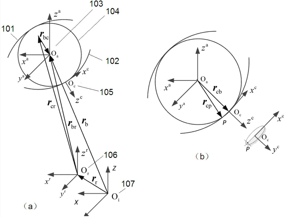
[0037] (1) Refer to figure 2 , first establish a series of coordinate systems on the angular contact ball bearing (GUPTA bearing analysis coordinate system, including the inertial coordinate system O i (X, Y, Z), rolling ball orientation coordinate system O a (x a ,y ...


PUM


Abstract

The invention discloses a high-speed angular contact ball bearing damage fault dynamic analysis method which is characterized by including the steps of (1) building a high-speed angular contact ball bearing dynamic model, (2) building a high-speed angular contact ball bearing damage fault model, (3) integrating the damage fault model with the high-speed angular contact ball bearing dynamic model to build a high-speed angular contact ball bearing damage fault dynamic model, and (4) carrying out numerical solution to obtain a dynamic response of a bearing under a fault situation and achieving dynamic analysis of a high-speed angular contact ball bearing damage fault. According to the method, three-dimensional motions, relative sliding and lubricating traction effects of the bearing element are taken into consideration, a comprehensive model of the damage fault is built in terms of mutual approach quantity, Hertz contact stiffness and contact load functions, analysis accuracy is improved, and the method for high-speed angular contact ball bearing damage fault dynamic researches is accurate.

Description

technical field [0001] The invention relates to an analysis method for damage faults of angular contact ball bearings with high speed (bearing rotation speed greater than or equal to 10000r / min). Background technique [0002] High-speed angular contact ball bearings have been widely used in important equipment such as high-end CNC machine tools and aero engines. The occurrence of damage and failure will lead to degradation of equipment performance, reduction of operating accuracy, and threat to operational safety. How to diagnose early and weak faults of such bearings in time to avoid major safety accidents is still a problem that plagues enterprises today. At present, the fault diagnosis research of rolling bearings basically starts from the inverse problem, lacking the support of the corresponding fault mechanism research. The dynamic analysis of damage fault is an important method for the study of rolling bearing fault mechanism. Through the dynamic analysis of rolling ...

Claims


Application Information

Patent Timeline
IPC IPC(8): G06F19/00
Inventor 何正嘉牛蔺楷曹宏瑞訾艳阳陈雪峰李兵张周锁
Owner XI AN JIAOTONG UNIV
Learn More