An improved lightning strike double-terminal traveling wave location method for transmission lines
A double-ended traveling wave positioning and transmission line technology, applied in the fault location and other directions, can solve the problems of reducing the lightning strike positioning accuracy, the impact of positioning accuracy, lack of line short-circuit faults and lightning strike fault distinction methods, etc.
- Summary
- Abstract
- Description
- Claims
- Application Information
AI Technical Summary
Problems solved by technology
Method used
Image
Examples
Embodiment 1
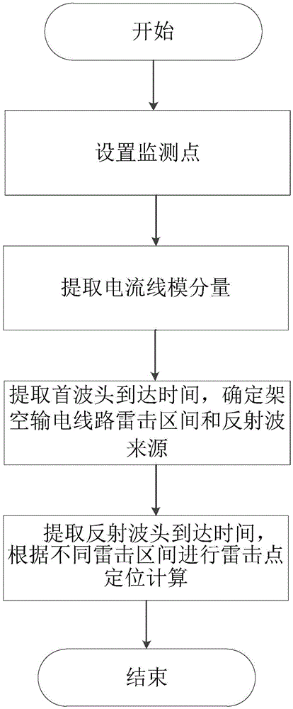
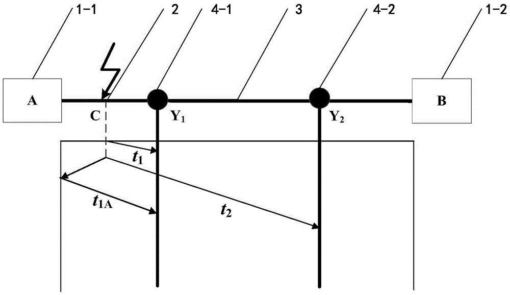
[0050] Such as figure 1 , 2 As shown, taking a 110kV, 60km overhead transmission line as an example, an improved transmission line lightning strike double-terminal traveling wave positioning method, the specific steps of the method are as follows:
[0051] (1) Set monitoring points
[0052] First, set up two monitoring points Y on the overhead transmission line 1 and Y 2 . The two monitoring points Y 1 and Y 2 It is installed at both ends of the overhead transmission line and distributed symmetrically. Each monitoring point Y 1 or Y 2 The average distance from the nearest substation is 10km, and the substation A on the left is set to the monitoring point Y 1 Between is monitoring area 1, monitoring point Y 2 The monitoring area 3 is between the substation B on the right and the monitoring point Y 1 to monitoring point Y 2 Between them is monitoring area 2.
[0053] (2) Extract the current line mode component
[0054] After step (1) is completed, set the distance b...
Embodiment 2
[0069] Such as figure 1 , 3As shown, an improved transmission line lightning strike double-terminal traveling wave positioning method is the same as in embodiment 1, wherein:
[0070] In step (2), set the distance between lightning strike point C and substation A on the left as 42.6km.
[0071] Monitoring point Y 1 The line-mode component of the current at x 1 Calculated as Figure 7 Shown, monitoring point Y 2 The line-mode component of the current at x 1 Calculated as Figure 8 shown.
[0072] In step (3), use wavelet transform to extract monitoring points Y respectively 1 and Y 2 The line-mode component of the current at x 1 Arrival time of the first wave in the medium, that is, t 1 109.5μs, t 2 is 25.4μs.
[0073] Then compare the monitoring point Y 1 and monitoring point Y 2 The line-mode component of the current at x 1 The polarity of the first wave head to determine the lightning strike interval: such as Figure 7 , 8 Shown, monitoring point Y 1 and m...
Embodiment 3
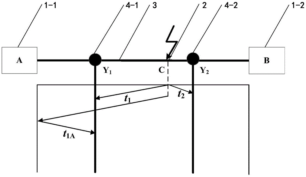
[0083] Such as figure 1 , 4 As shown, an improved transmission line lightning strike double-terminal traveling wave positioning method is the same as in embodiment 1, wherein:
[0084] In step (2), set the distance between lightning strike point C and substation A on the left as 57.4km.
[0085] Monitoring point Y 1 The line-mode component of the current at x 1 Calculated as Figure 9 Shown, monitoring point Y 2 The line-mode component of the current at x 1 Calculated as Figure 10 shown.
[0086] In step (3), use wavelet transform to extract monitoring points Y respectively 1 and Y 2 The line-mode component of the current at x 1 Arrival time of the first wave in the medium, that is, t 1 149.6μs, t 2 is 15.9μs.
[0087] Then compare the monitoring point Y 1 and monitoring point Y 2 The line-mode component of the current at x 1 The polarity of the first wave head to determine the lightning strike interval: such as Figure 9 , 10 Shown, monitoring point Y 1 an...
PUM
 Abstract
Description
Claims
Application Information
 - Generate Ideas
- Intellectual Property
- Life Sciences
- Materials
- Tech Scout
- Unparalleled Data Quality
- Higher Quality Content
- 60% Fewer Hallucinations
Browse by: Latest US Patents, China's latest patents, Technical Efficacy Thesaurus, Application Domain, Technology Topic, Popular Technical Reports.
© 2025 PatSnap. All rights reserved.Legal|Privacy policy|Modern Slavery Act Transparency Statement|Sitemap|About US| Contact US: help@patsnap.com


